

4. Start up the Delay Server and set up the system
Use the DTP menu to confi gure your Delay Server device
to the network.
Connect the Delay Server to your local KVM.
Press
CTRL+ALT+F3
to view the third available terminal.
At the login prompt, type
root
and press
Enter.
At the
password
prompt, type
DTVinabox
and press
Enter.
At the
#
prompt, type
stopdtp
and press
Enter.
At the
#
prompt, type
cd/home/
and press
Enter.
At the
#
prompt, type
sh confi gureds.sh
and press
Enter.
Access the Delay Server
Confi guration Menu
Attach an
extension
to the back
of each rail to match the depth of
your rack.
Attach the
rails
to the rack posts.
Slide the chassis into the rail.
To remove the chassis from
the rack:
Stand in front of the unit and pull
the chassis out as far as it will go.
On the
left
side, press down on
the plastic retaining mechanism.
On the
right
side, press up on
the plastic retaining mechanism.
Attach a
slide
to each side of the
chassis using (5) M4x10mm
screws on each side. Make sure
the plastic retaining mechanism
is located at the back of the
chassis.
front rack posts
rear rack posts
slide
rail
2. Rack mount the Delay Server
•
1 RU chassis (1)
•
Power cables (2)
Rack rail kit contains the following:
• Rails
(2)
• Slides
(2)
•
Short extensions (2)
•
Nut plates (6)
•
Bag of screws
1. Verify the contents
NX1012DS INSTALLATION
QUICK START
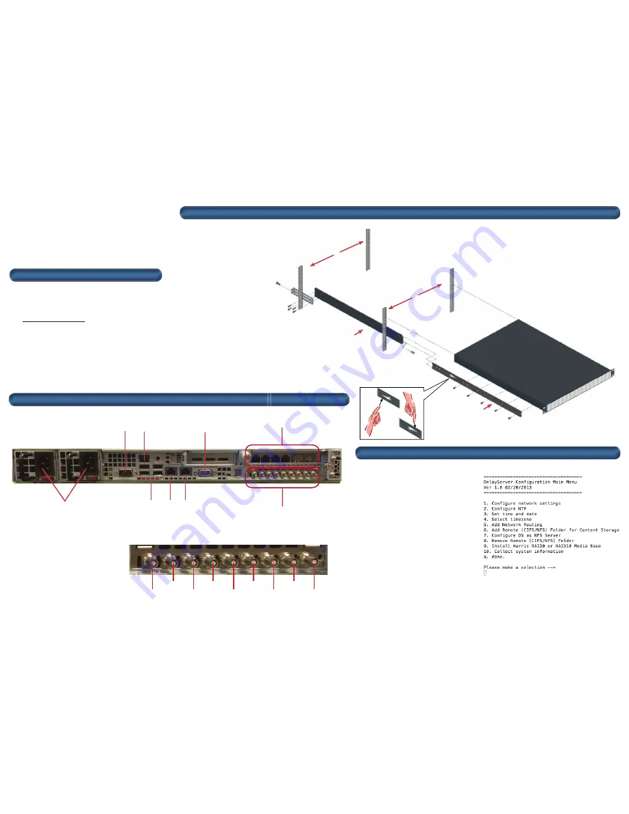
If the customer orders the
NX-ASI-44 card, place the card in
the PCIe x8 bottom slot.
Serial Port
RJ-45 IPMI LAN Port
VGA for Video
Power Supply (2)
USB (4)
Eth0 (NIC 1)
Eth1 (NIC 2)
Optional NX-GE-4
Optional NX-ASI-44
3. Attach the cables to the back panel
Reference Input
Input 0:0
Input 0:1
Input 0:2
Input 0:3
Output 0:0
Output 0:1
Output 0:2
Output 0:3


