

DDXI V1.00 DIGITAL DVI/VGA-KVM-EXTENDER
DDXI V1.00 DIGITAL DVI/VGA-KVM-EXTENDER
DDXI V1.00 DIGITAL DVI/VGA-KVM-EXTENDER
manual : http://www.ihse.de/pdf/b437-1w_e.pdf
manual : http://www.ihse.de/pdf/b437-1w_e.pdf
manual : http://www.ihse.de/pdf/b437-1w_e.pdf
1 Quick Setup
This section briefly describes how to install your KVM extender system and optimize the video
signals. Unless you are an experienced user, we recommend that you follow the full procedures
described in the rest of this manual. Refer to the command summary when following this procedure.
2 Installation
For first-time users, we recommend that you carry out a test placement, confined to a single room,
before commencing full installation. This will allow you to identify and solve any cabling problems,
and experiment with the KVM extender system more conveniently.
2.1 Package Contents
You should receive the following items in your extender package (all types) If anything is missing,
please contact Technical Support:
•
Extender Local/Remote unit.
•
2x 6V DC 12W universal power supply for Local/Remote unit.
•
2x DVI-I to VGA adapter (DVI-I dual link male to HD15 female) connector.
•
1x VGA to DVI-I adapter (HD15 male to DVI-I dual link female) connector.
•
Programming cable (DB9 female to RJ11 4p4c).
•
User manual (Quick Setup).
•
2x German-type power cord.
All PS/2 models are supplied with:
•
KVM CPU cable set (1.8m) with PS/2 (6-pin mini-DIN male-to-male) keyboard and mouse
connector and DVI-I video (DVI-I dual link male-to-male) connector
All USB types are supplied with:
•
DVI-I video cable (DVI-I dual link male-to-male)
•
USB cable (USB type A to type B)
•
5V DC 12W universal power supply for Remote unit
(only required when connecting two or more High Power USB
•
US-type power cord (additional)
2.2 System Setup
To install your DDXI - DVI KVM Extender system:
1.
Switch off all devices.
2.
Connect your keyboard, monitor(s) and mouse to the Remote unit as shown below (K439-1W),
(K437-1W/K438-1W) or (K442-3U/K443-3U).
These ports may also be attached to the CPU side of a KVM switch in order to
have a Remote CPU. However, if you are attempting to use the extender
between cascaded KVM switches this may not work. Please contact Technical
Support to discuss your application.
3.
Connect the interconnect cable to the INTERCONNECT socket(s) as shown below (K439-
1W), (K437-1W/K438-1W) or (K442-3U/K443-3U).
4.
Connect the 6V power supply to power the unit.
Only use the power supply originally supplied with this
equipment or a manufacturer-approved replacement.
5.
Using the supplied CPU KVM cable(s), connect the keyboard, monitor(s) and mouse
connectors on the computer (or KVM switch) to the corresponding connectors on the Local unit
as shown below (K439-1W), (K437-1W/K438-1W) or (K442-3U/K443-3U).
Ensure that you attach the keyboard and mouse connectors to the correct ports. The keyboard
connector is purple; the mouse connector is green.
If your PC does not have a PS/2 mouse port, an active serial converter will be
required
6.
For a dual access system, connect the keyboard, mouse and monitor for the Local console to the
appropriate ports on the Local unit. The ports may also be used to feed into a KVM switch.
7.
Connect the Interconnection cable from the Remote unit to the INTERCONNECT socket on
the Local unit as shown below (K439-1W), (K437-1W/K438-1W) or (K442-3U/K443-3U).
8.
Power up the system.
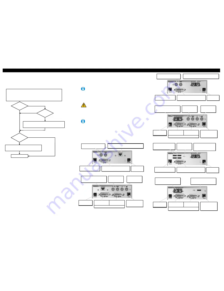
3 Device View (depending on device type)
K439-1W Remote Unit
K439-1W Local Unit
K437/K438-1W Remote Unit
K437/K438-1W Local Unit
K439-1W Remote Unit
K442-3U/K443-3U Local Unit
Install system
1.
Connect Remote unit to KVM.
2.
Connect Local unit to CPU or switch.
3.
Connect Local and Remote units with matching interconnection cable
(CATx, Multimode or Singlemode fiber).
4.
Power up the system.
Carry out
VGA Input Setup
procedure
(please follow the instructions on page 42).
Done
Yes
No
Do you have a
DVI monitor?
Do you have a
DVI source?
Do you
have a flat screen
(TFT)?
No
No
Yes
Yes
DVI-I Connector – DVI/VGA output –
connect to Remote console monitor
Connect to 6V
Power supply
Programming connector –
for firmware upgrades
Connect to PS/2 keyboard and
mouse using supplied cables
INTERCONNECT – carries video and data
signals – connect to Local unit with CATx cable
INTERCONNECT – carries video
and data signals – connect to
Remote unit
Connect to Local
console keyboard
and mouse
Connect to CPU’s
keyboard and
mouse sockets
Connect to Local
console monitor
Connect to 6V
Power supply
Programming
connector – for
firmware upgrades
Connect to CPU
video card output
INTERCONNECT – carries video
and data signals – connect to
Remote unit
Connect to Local
console keyboard
and mouse
Connect to CPU’s
keyboard and
mouse sockets
Connect to Local
console monitor
Connect 6V
Power supply
Programming
connector – for
firmware upgrades
Connect to CPU
video card output
DVI-I Connectors
4xUSB connectors for
keyboard, mouse and other
devices, for example, printer
INTERCONNECT – carries
video and data signals –
connect to Local unit
INTERCONNECT – carries video
and data signals – connect to
Remote unit
USB input – connect to CPU
Connect to Local
console monitor
Connect 6V
Power supply
Programming
connector – for
firmware upgrades
Connect to CPU
video card output
DVI-I Connectors
Connect 5V
Power supply for
USB high power
Connect to PS/2 keyboard and
mouse using supplied cables
INTERCONNECT – carries video and data
signals – connect to Local unit with Fibre cable
DVI-I Connector – DVI/VGA output –
connect to Remote console monitor
Connect to 6V
Power supply
Programming connector –
for firmware upgrades
DVI-I Connectors
DVI-I Connector – DVI/VGA output –
connect to Remote console monitor
Connect to 6V
Power supply
Programming connector –
for firmware upgrades
Carry out the
Monitor Setup
procedure (please
refer to its manual and see page 40 in this manual).


