


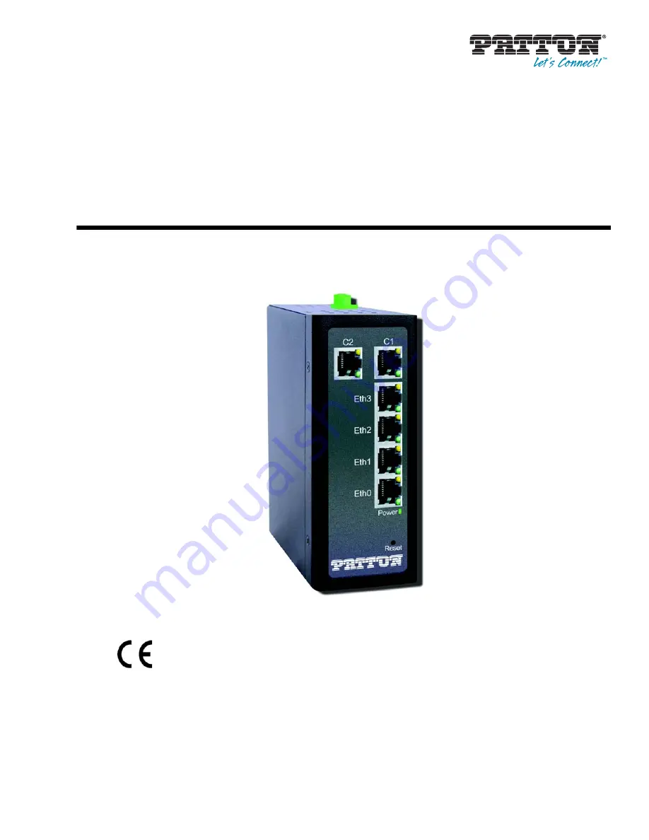
CopperLink Model CL1300MDE
Long Range Ethernet Extender
User Manual
Sales Office:
+1 (301) 975-1000
Technical Support:
+1 (301) 975-1007
E-mail:
WWW:
www.patton.com
Part Number:
07MCL1300MDE, Rev. A
Revised:
November 14, 2018
Important
This is a Class A device and is intended for use in a light industrial environment. It is
not intended nor approved for use in an industrial or residential environment.
REGULATORY MODEL NUMBER
: 03343D1-002
Start Installation
For Quick


