Check whether the power supply for the installation is correct (24VAC or
1.
DC) and turn the power off.
Remove the plug from the back of the Timer-Thermostat. Connect the 2
2.
thermostat wires to the plug and replace the plug back onto the connector.
If applicable, check whether the thermostat wires are connected to the
3.
heater clamps used for the On/Off control (option 1 in the schematics
below).
Mount the Timer-Thermostat using 2 screws of approx. 30 cm via the but-
4.
ton openings and turn on the power.
The thermostat will start up and will emit an acoustic signal.
5.
The flashing % symbol indicates whether any pre-programmed clock set-
6.
tings have been lost. E.g. as a result of a power failure. The % symbol will
disappear by programming the thermostat clock (see later on in this guide)
or - if you do not want to use the clock - by resetting the thermostat. You
can do this by shorting the two contact points to the right behind the right
button, e.g. using a small flathead screwdriver.
ATTENTION:
When the device does not work correctly, it may be necessary
to attach the resistor included to the heater’s clamp strip. Please consult the
manual of your heater and connect the Timer-Thermostat according to the sche-
matics above (option 2).
Please read this guide thoroughly and write down all the values you need to fill in
before starting programming.
ATTENTION
: The ICY1810 has already been pre-programmed. This programme
cannot be altered.
If the buttons are not touched for approx. 10s, the Timer-Thermostat will auto-
matically select the next function.
Terminology used in this guide:
COMFORT TEMPERATURE
:
temperature maintained during the day and
when user is present at night.
DORMANT TEMPERATURE
:
temperature maintained at night and when
user is absent.
ANTI-FROST TEMPERATURE
: temperature maintained when the Timer-
Thermostat has not been used for a longer
period of time, e.g. 12 hours.
Keep the left –(minus)-button pressed for 10s, until the display reads ‘P1’.
1.
Release the button. The display will now read ‘0’.
The Timer-Thermostat is now in programming mode and will request the
2.
first 2 digits of your PIN code.
Use the right +(plus)-button and left –(minus)-button to enter the correct
3.
number and wait approx. 10s after you’re finished.
The display will now read ‘P2’ and after 2s it will read ‘0’. The Timer-Ther-
4.
mostat will now request the second 2 digits of your PIN code. Now repeat
step 3.
If the PIN code is correct, continue with step 6. If the PIN code is incorrect,
5.
the Timer-Thermostat will beep and leave the programming mode.
The display will now read ‘t1’ and after 2s the pre-programmed ANTI-
6.
FROST TEMPERATURE will appear (e.g. ‘14’ °C). You can change the
value by repeating step 3.
The display will now read ‘t2’ and after 2s the pre-programmed MAXIMUM
7.
COMFORT TEMPERATURE will appear (e.g. ‘24’ °C). You can change the
value by repeating step 3.
The display will now read ‘t3’ and after 2s the pre-programmed COMFORT
8.
PERIOD will appear (e.g. ‘12’ x 10 minutes = 2 hours). You can change the
value by repeating step 3.
The display will now read ‘t4’ and after 2s the pre-programmed DORMANT
9.
TEMPERATURE will appear (e.g. ‘17’ °C). You can change the value by
repeating step 3.
The display will now read ‘t5’ and after 2s the pre-programmed DORMANT
10.
PERIOD will appear (e.g. ‘12’ hours). You can change the value by repeat-
ing step 3.
Continue with step 15 for the ICY1830/35/50 Timer-Thermostat.
Continue with step 11 for the ICY1840/45.
The display will now read ‘t6’ and after 2s the HOURS of START COM-
11.
FORT will appear (e.g. ‘10’ o’clock). When the clock is not being used, the
display will now read ‘--’. You can change the value by repeating step 3.
By using the –(minus)-button to go to the minimum ‘--’, the clock will be
disabled. When the clock is disabled, continue with step 15. When the
clock is enabled, continue with step 12.
The display will now read ‘t7’ and after 2s the MINUTES of START
12.
COMFORT will appear (e.g. ‘58’ minutes). You can change the value by
repeating step 3.
The display will now read ‘t8’ and after 2s the HOURS of REAL TIME will
13.
appear (e.g. ‘7’ o’clock). You can change the value by repeating step 3.
The display will now read ‘t9’ and after 2s the MINUTES of REAL TIME will
14.
appear (e.g. ‘45’ minutes). You can change the value by repeating step 3.
The display will now read ‘P1’ and after 2s the first 2 digits of the pre-
15.
programmed PIN code will appear (e.g. ‘11’). You can change the value by
repeating step 3.
The display will now read ‘P2’ and after 2s the second 2 digits of the pre-
16.
programmed PIN code will appear (e.g. ‘12’). You can change the value by
repeating step 3.
The Timer-Thermostat will then automatically store any changes in the memory
and will beep and leave the programming mode.
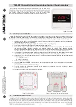
Installation
ICY
HEATER
ICY
HEATER
resistance
ICY1830/35/40/45/50 Programming guide
option 1
option 2
ICY
18xx
T i m e r - T h e r m o s t a t s
User Manual
a n d i n s t a l l a t i o n g u i d e
I.C.Y. B.V.
Postbus 193, 8530 AD Lemmer, The Netherlands
T.:0031 514 563424, Fax.: 0031 514 564252
www.icy.nl
© 2009 ICY B.V.
rev.: 00120509