background image


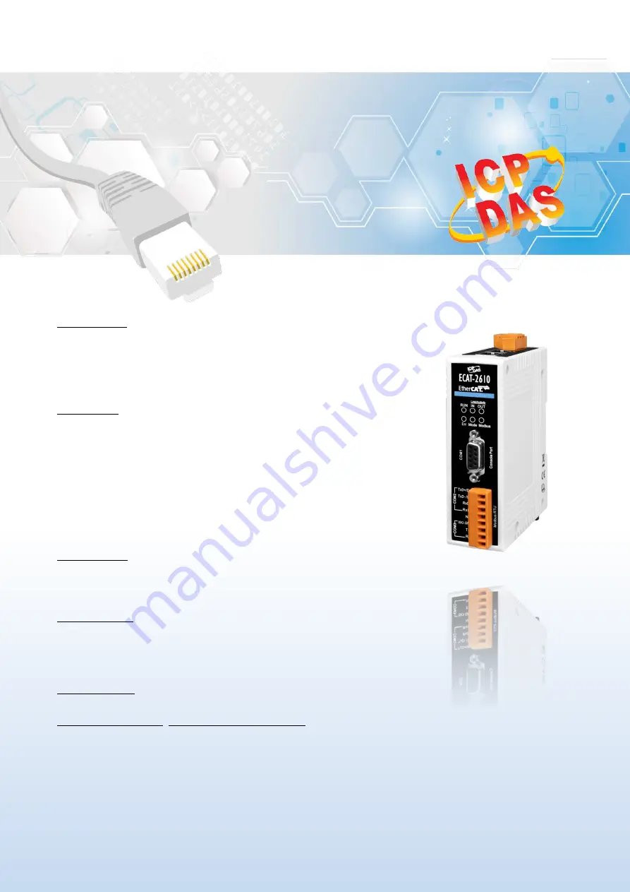
ECAT-2610 EtherCAT to Modbus 
RTU Gateway 

User Manual


English Ver. 1.0, Dec. 2017 


WARRANTY 

All products manufactured by ICP DAS are warranted against 

defective materials for a period of one year from the date of 

delivery to the original purchaser. 


WARNING 

ICP DAS assumes no liability for damages consequent to the use 

of this product. ICP DAS reserves the right to change this manual 

at any time without notice. The information furnished by ICP 

DAS is believed to be accurate and reliable. However, no 

responsibility is assumed by ICP DAS for its use, nor for any 

infringements of patents or other rights of third parties resulting 

from its use. 


COPYRIGHT 

Copyright © 2017 by ICP DAS. All rights are reserved. 


TRADEMARK 

Names are used for identification only and may be registered 

trademarks of their respective companies. 


CONTACT


US 

If you have any questions, please feel free to contact us via email at:   

[email protected], [email protected] 


Summary of Contents for ECAT-2610

Page 1: ...e this manual at any time without notice The information furnished by ICP DAS is believed to be accurate and reliable However no responsibility is assumed by ICP DAS for its use nor for any infringements of patents or other rights of third parties resulting from its use COPYRIGHT Copyright 2017 by ICP DAS All rights are reserved TRADEMARK Names are used for identification only and may be registere...

Page 2: ...TTING STARTED 15 3 1 FACTORY DEFAULT SETTINGS 15 3 2 CONNECTING THE POWER AND THE HOST PC 16 3 3 CONFIGURATION AND OPERATION 18 3 3 1 Module Status and Error Mode 20 4 MODBUS RTU DEVICE SETUP 22 4 1 CONFIGURE THE MODBUS RTU DEVICE 23 4 2 CONFIGURING AND UPLOADING 26 4 3 TESTING MODBUS RTU DEVICE 32 5 MODBUS INFORMATION 36 01 0X01 READ THE STATUS OF THE COILS READBACK DOS 39 02 0X02 READ THE STATUS...

Page 3: ...72 APPENDIX 75 A1 HOW DO I GET THE MODBUS RTU COMMAND VIA DCON UTILITY 75 A2 CONFIGURATION FILES REFERENCE 76 INIT txt 76 115200_N81_INIT txt 77 9600_N81 txt 77 19200_N82 txt 79 38400_E81 txt 79 57600_O81 txt 79 DIO_Addr01_0 Addr01_1 DIO_Addr01_2 txt 80 DIO_Addr01_3 txt 81 DIO_Addr01_4 txt 82 DIO_Addr01_5 txt 84 DIO_Addr01_6 txt 86 DIO_Addr01_7 txt 87 DA_Addr02_1 txt 88 DA_Addr02_2 txt 89 DA_Addr0...

Page 4: ...information Keep the shipping materials and overall package in case you want to ship the module back in the future More Information Manual QuickStart Datasheet http ftp icpdas com pub cd fieldbus_cd ethercat slave ecat 2000 manual XML Device Description ESI http ftp icpdas com pub cd fieldbus_cd ethercat slave ecat 2000 software FAQ http www icpdas com root support faq faq html ECAT 2610 x 1 Quick...

Page 5: ... any changes to the device Just connect configure and it s finished The ECAT 2610 Communicator is a proven and trusted protocol converter gateway that connects non networked industrial devices and equipment to EtherCAT The gateway performs an intelligent protocol conversion and presents the serial data to the Master PLC Controller as easily processed I O data Figure 1 1 The System diagram of Ether...

Page 6: ... automation devices into modern EtherCAT communication structures Requires no hardware or software changes to be made to the connected device Compatible with all PLCs with EtherCAT support Performs complete serial protocol conversion no PLC function blocks required Supports maximum 128 input and 128 output bytes data Supports maximum Baud Rate 115200 bps 1 2 Block Diagram The block diagram of the ...

Page 7: ...e constantly vulnerable to Electrostatic Discharge ESD which becomes worse in a continental climate area ECAT 2610 module feature a new design for the frame ground which provides a path that bypasses ESD resulting in an enhanced ESD protection capability and ensuring that the module is more reliable 2 EtherCAT Interface ECAT 2610 module is equipped with two RJ 45 EtherCAT Interface ports IN is Eth...

Page 8: ...s in state INIT Blinking The device is in state PRE OPERARIONAL Single Flash The device is in state SAFE OPERARIONAL On The device is in state OPERARIONAL Link Activity IN OUT Green Off No link Blinking Link and activity On Link without activity 6 COM2 COM3 Modbus RTU 5 COM1 Console Port 3 EtherCAT bus Status Indicators 4 ECAT 2610 Status Indicators Figure 2 2 Front panel of ECAT 2610 ...

Page 9: ...figuration file or configuration file error Flashing for 4 sec Configuration CRC error Modbus Green Off No Modbus Command Flashing for 1 sec Normal 5 COM1 Console Port DB9 Male Configuration Diagnostic Port The more detailed information of pin assignments for the PC COM Port refer to Section 2 3 Pin Assignments 6 COM2 COM3 Modbus RTU Connect to Modbus RTU devices The more detailed information of p...

Page 10: ...ace RS 232 The RS 232 RS 422 and RS 485 cannot be used simultaneously TxD RxD GND TxD TxD RxD RxD Data Data RS 422 RS 485 Power Input Redundant Input Range 12 48 VDC Power Consumption 0 1 A 24 VDC Protection Power reverse polarity protection Connector 3 Pin Removable Terminal Block 5 08 mm Mechanical Dimensions H x W x D 110 mm x 90 mm x 33 mm Installation DIN Rail Mounting Environment Operating T...

Page 11: ...nterface COM1 Console Port COM2 COM3 Modbus RTU Pin Assignment F G GND PWR IN OUT Pin Assignment Terminal No 01 RxD 02 TxD 03 04 GND 05 Terminal No Pin Assignment COM2 TxD D TxD D RxD RxD N A COM3 ISO GND TxD RxD NOTE The RS 232 RS 422 and RS 485 cannot be used simultaneously Terminal No Pin Assignment 06 07 08 09 ...

Page 12: ...ogether to reduce common mode voltage between devices 2 Twisted pair cable must be used for the DATA wires 3 Both two ends of the cable may require a termination resistor connected across the two wires DATA and DATA Typically 120 Ω resisters are used 4 The Data and B pins are positive voltage pins and Data and A pins are negative voltage pins in the above figure The B A pins may be defined in anot...

Page 13: ...ule and connect the ECAT 2610 to Host PC 2 Short the TxD and RxD pins on the COM3 to Init mode 3 Run the 7188ECAT exe and power on the ECAT 2610 module to verify that enter the init mode 4 Disconnect the TxD and RxD pins on the COM3 to normal mode 5 Erase the EEPROM and upload new configuration file to EEPROM 6 Reboot the ECAT 2610 module to work in normal mode Refer to Chapter 6 Diagnostic Operat...

Page 14: ...ghts Reserved 14 2 6 Dimensions The following diagrams provide the dimensions of the ECAT 2610 module and can be used as a reference when defining the specifications for any custom enclosures All dimensions are in millimeters Left Side Right Side Front Rear Top Bottom ...

Page 15: ... to Chapter 8 Object Description and Parameterization for more detail about InTxPDO and OutRxPDO OutRxPDO 4 OutRxPDO n InTxPDO n N 0 1 2 3 Run LED Red Refer to Section 2 1 Appearance for more detail about LED indicators IN LED Flashing Green Mode LED Flashing Green Baud Rate 115200 Refer to Section 4 2 Configuring and Uploading for more detail about Baud Rate Data Format and Command Settings Parit...

Page 16: ...y Anti Virus firewall is properly configured to allow incoming connections or temporarily disable these functions NOTE Step 2 Apply power to the ECAT 2610 module Connect the PWR pin to positive terminal on a 12 48 VDC power supply and connect the GND pin to the negative terminal Connect the Host device to the IN Port on ECAT 2610 module Attaching an ESC EtherCAT Slave Controller directly to an off...

Page 17: ...odbus RTU Gateway Copyright 2017 ICP DAS CO Ltd All Rights Reserved 17 Step 3 Verify that LEDs indicator on the ECAT 2610 module is given as follows IN Green Flashing Mode Green Flashing RUN Red Run IN Figure 3 2 2 ...

Page 18: ...l file to the Master Tools installation folder as indicated in the table below Software Default Path Beckhoff EtherCAT Configuration C EtherCAT Configurator EtherCAT Beckhoff TwinCAT 3 X C TwinCAT 3 x Config Io EtherCAT Beckhoff TwinCAT 2 X C TwinCAT Io EtherCAT Beckhoff TwinCAT 2 X is most commonly used EtherCAT Master software to operate ECAT 2610 module Step 2 Automatic Scanning The EtherCAT sy...

Page 19: ...lick on the branch of the EtherCAT Box you wish to configure Click TxPDO to get and configure state NOTE For detailed information about the status_low and status_hi of ECAT 2610 refer to Section 3 3 1 Module Status and Error Mode Scanning in the configuration I O Devices right click Scan Devices Figure 3 2 3 In the right hand of the windows check In000 is 0x80 status_low and In001 is 0xC0 status_h...

Page 20: ... module will enter the error mode the details as below The Err LED indicator will illuminate as follows Check results of the Baud rate and Data Format etc are given in status_low as follows InTxPDO 00 status_low 0x80 normal settings the status_low is defined as follows D7 D6 D5 D4 D3 D2 D1 D0 1 0 CRC Error Delay Error Stop Bit Error Parity Bit Error Baud Rate Error Debug Mode EEPROM CRC Error Deal...

Page 21: ... InTxPDO 01 status_hi 0xC0 normal settings the status_hi is defined as follows D7 D6 D5 D4 D3 D2 D1 D0 1 1 0 0 0 Cmd Fun Error Cmd Length Error CmdNum Error Command Function Error refer to Chapter 5 Modbus Information for more detail Command Length Error refer to Chapter 5 Modbus Information for more detail Command Number Error Valid Range 0 to 200 Max ...

Page 22: ...Baud Rate and Data Format etc and how to modify the configuration file to control the Modbus RTU device The following illustration is a quick reference of configuration and setup process for you to set up Modbus RTU device Figure 4 1 Modbus RTU Device Setup Configure the Modbus RTU Device Set Net ID Baud Rate and Data Format see Section 4 1 for more detail Configuration file Settings Use ECAT 2610...

Page 23: ...D Baud Rate and Data Format etc Step 1 Connect the Modbus device e g M 7050D optional to Host PC Step 2 Download and Run the DCON Utility Pro Software For ICP DAS Modbus RTU slave device the DCON Utility Pro is free download and installation it can be obtained from the ICP DAS web site at http ftp icpdas com pub cd 8000cd napdos driver dcon_utility to search modules out and configure the searched ...

Page 24: ... Search Module Click COM Port button to select COM Port e g COM1 depends on Host PC COM Port that connects to M 7050D and click OK button Click Start Search button to search Modbus RTU device When the Modbus RTU device is found click Stop Search button Figure 4 1 2 Figure 4 1 3 Figure 4 1 4 ...

Page 25: ...rmat Click the module name to open the configuration dialog box Set the Address Net ID Baud Rate and Data Format for Modbus RTU device Click Set Module Configurations button to save the new configuration NOTE If there are multiple Modbus RTU devices on the RS 485 network each of them needs be assigned with a unique Net ID Figure 4 1 5 ...

Page 26: ...from the companion CD or ICP DAS web site at CD Napdos ECAT 2000 Software http ftp icpdas com pub cd fieldbus_cd ethercat slave ecat 2000 software After all the software is copied to the Host PC e g E the content of 7188ECAT folder should be as follows Configuration files Reference for DI DO AD DA etc Refer to Section A2 Configuration Files Reference for more detail Execution file Control file for...

Page 27: ...odbus RTU Gateway Copyright 2017 ICP DAS CO Ltd All Rights Reserved 27 Step 3 Execute the ECAT 2610 Configuration Tool exe Double click the ECAT 2610 Configuration Tool exe to open configuration toolkit Figure 4 2 2 ...

Page 28: ... from the relevant drop down options depending on the Modbus RTU device e g M 7050D Step 5 Configure the Modbus command and update mode Type the Modbus command of write 8 Digital Output channels as follows 1 Set the appropriate Slave ID Function Code Start Address and Quantity settings from the relevant field depending on the Modbus RTU device e g M 7050D 2 Set the update mode from the Mode drop d...

Page 29: ...ode Start Address and Quantity settings from the relevant field depending on the Modbus RTU device e g M 7050D 5 Set the update mode from the Mode drop down options 6 Click the NEXT button to add a Modbus command to Input TxPDO 0x00 Step 6 Click the CONNECT to connect the ECAT 2610 Verify that status column shows Connecting and UPLOAD CONFIGURATION button is unlocked Figure 4 2 6 Figure 4 2 5 ...

Page 30: ...GURATION button to upload the configuration file to ECAT 2610 and the status column will be displayed the progress of the upload 2 The ECAT 2610 CFG TOOL dialog box will be displayed asking you to reboot the ECAT 2610 module 3 Power off and power on the ECAT 2610 module and click the OK button to continue Figure 4 2 7 Figure 4 2 8 ...

Page 31: ... module when the upload is successful 5 Power off and power on the ECAT 2610 module and click the OK button to complete the upload Note If the upload configuration via ECAT 2610 configuration tool exe is failed then the manually configuration file and upload is required to make the module working again refer to A3 Manually Configure and upload for more detail Figure 4 2 9 ...

Page 32: ...vice Here the M 7050D module is used as an example For other Modbus RTU device refer to the specific Quick Start Guide or User Manual for that Modbus RTU device Step 1 Connect the Modbus RTU Device Keep up network connection status for your ECAT 2610 module refer to Section 3 2 Connecting the Power and the Host PC for more details Connect the ECAT 2610 module with Modbus RTU device e g M 7050D opt...

Page 33: ...ration and Operation for more details Step 3 Automatic Scanning Switch on the operating voltage open the TwinCAT System Manager Config mode and scan in the devices below the picture Acknowledge all dialogs with OK so that the configuration is in FreeRun mode Scanning in the configuration I O Devices right click Scan Devices Figure 4 3 2 NOTE The EtherCAT system must be in a safe de energized state...

Page 34: ...e branch of the EtherCAT Box you wish to configure ECAT 2610 Click Inxxx and Outxxx to get and configure state Verify the test results of the DO functions for M 7050D module in the following manner In the left hand of the window click the Out000 In the right hand of the window click the Online Click the Write to open the Set value Dialog dialog box Figure 4 3 3 Figure 4 3 4 ...

Page 35: ...pyright 2017 ICP DAS CO Ltd All Rights Reserved 35 In the Set value Dialog dialog box enter the 0xff in the Hex field configure all DO is ON and click the OK Check all DO LED on the M 7050D module are lighting Figure 4 3 5 Figure 4 3 6 ...

Page 36: ...h only one device the master client can initiate transactions called queries The other devices slaves servers respond by supplying the requested data to the master or by taking the action requested in the query A query from a master will consist of a slave address a function code defining the requested action any required data and an error checking field A response from a slave consists of fields ...

Page 37: ...s are between 1 and 255 The slave uses the same function code as the request to answer it Only when an error occurs in the system will the highest bit of the function code is set to 1 Hence the master will know whether the message has been transmitted correctly or not Code Function Reference Address 01 0x01 Read the Status of the Coils Readback DOs 0xxxx 02 0x02 Read the Status of the Input Reads ...

Page 38: ...the master does not require this information the data field can be empty Reference Address Description 0xxxx Read Write Discrete Outputs or Coils A 0x reference address is used to output device data to a digital output channel 1xxxx Read Discrete Inputs The ON OFF status of a 1x reference address is controlled by the corresponding digital input channel 3xxxx Read Input Registers A 3x reference reg...

Page 39: ...nds on your slave device for more details Byte 02 high byte Byte 03 low byte 04 05 Number of Points Channels 2 Bytes Byte 04 high byte Byte 05 low byte Response Byte Description Size Value 00 Net ID Station Number 1 Byte 1 to 247 01 Function Code 1 Byte 0x01 02 Byte Count 1 Byte Byte Count of the Response n Points 7 8 03 Data n Bytes n 1 Byte 03 data bit 7 to 0 n 2 Byte 04 data bit 15 to 8 n m Byt...

Page 40: ...or more details Byte 02 high byte Byte 03 low byte 04 05 Number of Points Channels 2 Bytes Byte 04 high byte Byte 05 low byte Response Byte Description Size Value 00 Net ID Station Number 1 Byte 1 to 247 01 Function Code 1 Byte 0x02 02 Byte Count 1 Byte Byte Count of Response n Points 7 8 03 Data n Bytes n 1 Byte 03 data bit 7 to 0 n 2 Byte 04 data bit 15 to 8 n m Byte m 2 data bit 8m 1 to 8 m 1 E...

Page 41: ...s Byte 02 high byte Byte 03 low byte 04 05 Number of 16 bit Registers Channels 2 Bytes Word Count Byte 04 high byte Byte 05 low byte Response Byte Description Size Value 00 Net ID Station Number 1 Byte 1 to 247 01 Function Code 1 Byte 0x03 02 Byte Count 1 Byte Byte Count of the Response n Points x 2 Bytes 03 Register Values n Bytes Register Values n 2 Byte 03 high byte Byte 04 low byte n m Byte 03...

Page 42: ... byte Byte 03 low byte 04 05 Number of 16 bit Registers Channels 2 Bytes Word Count Byte 04 high byte Byte 05 low byte Response Byte Description Size Value 00 Net ID Station Number 1 Byte 1 to 247 01 Function Code 1 Byte 0x04 02 Byte Count 1 Byte Byte Count of the Response n Points x 2 Bytes 03 Register Values n Bytes Register Values n 2 Byte 03 high byte Byte 04 low byte n m Byte 03 high byte Byt...

Page 43: ...ow byte 04 05 Output Value 2 Bytes 0xFF 00 sets the output to ON 0x00 00 sets the output to OFF All other values are invalid and will not affect the coil Byte 04 high byte Byte 05 low byte Response Byte Description Size Value 00 Net ID Station Number 1 Byte 1 to 247 01 Function Code 1 Byte 0x05 02 03 DO Address 2 Bytes The value is the same as Bytes 02 03 of the Request 04 05 Output Value 2 Bytes ...

Page 44: ...e device for more details Byte 02 high byte Byte 03 low byte 04 05 Register Value 2 Bytes Register Value Byte 04 high byte Byte 05 low byte Response Byte Description Size Value 00 Net ID Station Number 1 Byte 1 to 247 01 Function Code 1 Byte 0x06 02 03 AO Address 2 Bytes The value is the same as Bytes 02 03 of the Request 04 05 Register Value 2 Bytes The value is the same as Bytes 04 05 of the Req...

Page 45: ...nt 1 Byte n Points 7 8 07 Output value n Bytes A bit corresponds to a channel A value of 1 for a bit denotes that the channel is ON while a value of denotes that the channel is OFF n 1 Byte 07 data bit 7 to 0 n 2 Byte 08 data bit 15 to 8 n m Byte m 6 data bit 8m 1 to 8 m 1 Response Byte Description Size Value 00 Net ID Station Number 1 Byte 1 to 247 01 Function Code 1 Byte 0x0F 02 03 Starting DO A...

Page 46: ...Word Count Byte 04 high byte Byte 05 low byte 06 Byte Count 1 Byte n Points x 2 Bytes 07 Register Values n Bytes Register Values n 2 Byte 03 high byte Byte 04 low byte n m Byte 03 high byte Byte 04 low byte Byte m 1 high byte Byte m 2 low byte Response Byte Description Size Value 00 Net ID Station Number 1 Byte 1 to 247 01 Function Code 1 Byte 0x10 02 03 Starting AO Address 2 Bytes The value is th...

Page 47: ...e See Figure 6 1 1 the ECAT 2610 module will enter the Init Mode debug mode it will bypass the EEPROM and stop execute command User can erase the EEPROM and upload new configuration file to EEPROM the details as below Step 1 Connect the TxD to RxD Pins to Init Mode Power off the ECAT 2610 module Connect the PC COM Port of ECAT 2610 to the COM Port of Host PC using the CA 0915 download cable Connec...

Page 48: ...ty 1 In the Search field type cmd and the press Enter to open the Command Prompt window 2 A Command Prompt window will be displayed and type e 7188ECAT folder location on your hard drive and the press Enter 3 Type cd 7188ecat and the press Enter 4 Type execcom4 and the press Enter to auto run the 7188ECAT exe program Figure 6 1 3 Figure 6 1 2 ...

Page 49: ...d READ1 Read EEPROM Factory Debug READ2 Read EEPROM Factory Debug SHOW1 Show status Factory Debug SHOW2 Show InTxPDO 0 to InTxPDO 127 Factory Debug SHOW3 Show OutRxPDO 0 to OutRxPDO 127 Factory Debug SHOW4 Show debug information Factory Debug ERASE Erase EEPROM Download Only the CTRL F4 and ERASE are designed to download configuration file commands txt to EEPROM The other commands are designed for...

Page 50: ...Upload new configuration file to EEPROM 1 Type Erase and the press Enter to erase the EEPROM 2 Reboot the ECAT 2610 module 3 Pressing keyboard Ctrl F4 to download new configuration file commands txt to the ECAT 2610 module Key in erase and press Enter Figure 6 1 6 Figure 6 1 7 Starting upload ...

Page 51: ...ght 2017 ICP DAS CO Ltd All Rights Reserved 51 4 Reboot the ECAT 2610 module 5 Then click the X icon on the right top corner of the window to close it The download is complete and new configuration file will be displayed here Figure 6 1 8 ...

Page 52: ...hronize the time in all local bus devices within a very narrow tolerance rang Further and more detailed information about EtherCAT in general and distributed clocks in particular can be found under http www ethercat org 7 1 Modbus RTU Timing Write DO Refer to A1 How do i get the Modbus RTU command via DCON Utility for send command to M 7050 module as follows Send command string 01 0F 00 00 00 08 0...

Page 53: ...00 08 01 00 FE 95 to the M 7050 first then read response 01 0F 00 00 00 08 54 0D from the M 7050 The send_ then_read process will not stop and repeat one by one The hardware timing of one send read is given as follows Send 01 0F 00 00 00 08 01 00 FE 95 is about 1 ms Read 01 0F 00 00 00 08 54 is about 1 ms The send_then_read is about 5 ms The read_N to send_N 1 is about 2 ms One send_read_cycle is ...

Page 54: ...and Upload for send command to M 7050 module as follows Send command string 01 02 00 00 00 07 39 C8 Receive response string 01 02 01 00 A1 88 NOTE The 39 C8 and A1 88 are check sum bytes Refer to A3 Manually Configure and Upload to download DIO_Addr01_1 txt see Figure 7 1 5 to the ECAT 2610 module Figure 7 1 4 Figure 7 1 5 ...

Page 55: ...d response 01 02 01 00 A1 88 from the M 7050 The send_ then_read process will not stop and repeat one by one The hardware timing of one send read is given as follows Send 01 02 00 00 00 07 39 C8 is about 0 8 ms Read 01 02 01 00 A1 88 is about 0 7 ms The send_then_read is about 4 ms The read_N to send_N 1 is about 2 ms One send_read_cycle is about 4 2 6 ms Figure 7 1 6 ...

Page 56: ... 00 08 01 00 FE 95 read 01 0F 00 00 00 08 54 0D Read DI Command_02 send 01 02 00 00 00 07 39 C8 read 01 02 01 00 A1 88 The M 7050 will send_read command_01 first then send_read command_02 The hardware timing of Write DO Command_01 Read DI Command_02 is given as follows One Write DO Command_1 Read DI Command_02 about 13 2 ms Figure 7 1 7 ...

Page 57: ...0 module will auto detect and synchronized to DC signal at every first command The cycle time of DIO_Addr01_0 txt is about 7 ms and the cycle time of DIO_Addr01_1 txt is about 13 2 ms If the DC is set to 20 ms the cycle time of DIO_Addr01_0 txt is given as follows Sync to DC at every first command Figure 7 1 8 ...

Page 58: ...s given as follows One command_1 command_02 about 13 2ms If the DC cycle time is set to 10 ms 13 2 ms the ECAT 2610 will sync to DC at every first command So the timing diagram of DC 10 mS is as same as DC 20 ms above The total command cycle time can be greater then DC cycle time without any problem Sync to DC at every first command Figure 7 1 9 ...

Page 59: ...s Reserved 59 7 2 DC Configuration and Operation The image below shows an example of the setup for Distributed Clocks DC test DC is active One DI ECAT 2052 One DO1 M 7055 slave1 another DO2 M 7055 slave2 DO1 DI DO2 DI Figure 7 2 1 The setup for Distributed Clocks DC test ...

Page 60: ...Set the DC Synchron in the TwinCAT 3 0 software follow the procedure described below Step 1 Scan for devices Step 2 DC mode settings for ECAT 2610 I O Devices Right click Scan Click Box1 and Box2 ECAT 2610 on left side Click DC on Right side Select DC Synchron Figure 7 2 2 Figure 7 2 3 ...

Page 61: ...ll Rights Reserved 61 Step 3 Activate PLC PCL Right click Add New Item on left side Enter the project name e g Task1 Clike Add Task1 Right click Activate Boot Project See message under MAIN tab Build succeeded and write code Figure 7 2 4 Figure 7 2 5 Figure 7 2 6 ...

Page 62: ...AS CO Ltd All Rights Reserved 62 Step 4 Mapping M 7055 Output variables Step 5 Cycle time settings Click PlcTask Click Task Set cycle time to 10 ms Figure 7 2 7 Figure 7 2 8 Double click MAIN M7055_DO_SLAVE1_0 Select Out000 from Box1 ECAT 2610 Click OK ...

Page 63: ...EtherCAT to Modbus RTU Gateway Copyright 2017 ICP DAS CO Ltd All Rights Reserved 63 Step 6 Run PLC Click OK Click Activate Configuration symbol Figure 7 2 9 Figure 7 2 11 Click OK Figure 7 2 10 ...

Page 64: ...EtherCAT to Modbus RTU Gateway Copyright 2017 ICP DAS CO Ltd All Rights Reserved 64 Click Login symbol Click Start symbol Figure 7 2 12 Figure 7 2 13 ...

Page 65: ...eserved 65 If the DC Synchron is disable the DO1 and DO2 is independent the typical timing diagram is about some ms given as follows DO1 to DO2 2 ms DO1 to DO2 5 ms The worse case of DO1 to DO2 is about 7 ms refer to Section 7 1 Modbus RTU Timing Figure 7 2 13 Figure 7 2 14 ...

Page 66: ...ts Reserved 66 If the DC Synchron is active the DO1 and DO2 will be sync to DC together the typical timing diagram is about some us given as follows DO1 to DO2 6 us DO1 to DO2 100 us In general the DO1 to DO2 timing difference is about some us Figure 7 2 15 Figure 7 2 16 ...

Page 67: ...smit PDO mapping 00h Number of entries UINT8 R Refer to following table 8 1 1C00h Sync Manager Communication Type 00h Number of entries UINT8 R 04h 01h Maibox write UINT8 R 01h 02h Maibox read UINT8 R 02h 03h Process Data Out UINT8 R 03h 04h Process Dat in UINT8 R 04h 1C12h Sync Manager Rx PDO Assign 00h Number of entriesa UINT8 R No of assigned RxPDO 0 1 01h Assigned RxPDO UINT8 R Assigned to RxP...

Page 68: ...127 UINT8 RO NOTE The gateway will only create the number of objects needed to hold the subnetwork configuration Output Buffer Index Object Name Sub Index Meaning Data type Flags 2100h Outputs 00h No of entries UINT8 RO 01h Output byte 0000 UINT8 R W 02h Output byte 0001 UINT8 R W 80h Output byte 0127 UINT8 R W NOTES 1 For consistency reasons data declared as I O data will be read only 2 The gatew...

Page 69: ...way Copyright 2017 ICP DAS CO Ltd All Rights Reserved 69 9 Applications 9 1 ECAT Family of ICPDAS For more information please visit the EtherCAT Selection Guide web site The system diagram of ECAT Motion Slave is given as follows ...

Page 70: ...EtherCAT to Modbus RTU Gateway Copyright 2017 ICP DAS CO Ltd All Rights Reserved 70 The system diagram of ECAT Motion Master is given as follows The system diagram of ECAT Gateway is given as follows ...

Page 71: ...EtherCAT to Modbus RTU Gateway Copyright 2017 ICP DAS CO Ltd All Rights Reserved 71 The system diagram of ECAT family is given as follows ...

Page 72: ...rCAT to Modbus RTU Gateway Copyright 2017 ICP DAS CO Ltd All Rights Reserved 72 9 2 ODM is Welcome ICPDAS has rich platform for ECAT master solution as follows ICPDAS has slave simple_IO solution as follows ...

Page 73: ...EtherCAT to Modbus RTU Gateway Copyright 2017 ICP DAS CO Ltd All Rights Reserved 73 ICPDAS has slave complex_IO ESC uC ARM or MIPS 32 bit solution as follows ICPDAS has rich software package as follows ...

Page 74: ...EtherCAT to Modbus RTU Gateway Copyright 2017 ICP DAS CO Ltd All Rights Reserved 74 ICPDAS has rich software environment as follows ICPDAS has rich software utility as follows ...

Page 75: ...Section 4 1 Configure the Modbus RTU Device for more details click Command Line button to open the Tool for Terminal Command dialog box Select the appropriate COM Port Baud Rate Format and Address settings from the relevant drop down options as shown below Figure A1 1 Select the module name from the Select ID drop down options then all command will be given in point 4 Select the command and the Mo...

Page 76: ... of which will be described in more detail below You can refer to these examples of configuration files to effectively set your configuration file commands txt The content of more commands folder should be as follows INIT txt The INIT txt is default settings commands txt default command is FF 03 00 00 00 01 that used to read the status_low and status_hi of ECAT 2610 module refer to Section 3 3 1 M...

Page 77: ...he 9600_N81 txt support 2 typical Modbus RTU commands Write DO and Read DI as follows For Example Baud rate 9600 Parity N None Stop Bit 1 Number of command 2 01 Modbus RTU Command PDO Addr Update Mode 01 0F 00 00 00 08 01 00 00 00 This command will read OutRxPDO 00 and send Module RTU command to DO module To get command of write DO is given as follows see Figure A2 2 1 Select module M7000 DI DO mo...

Page 78: ...PDO Addr Update Mode 01 02 00 00 00 07 00 00 This command will read DI from module first then write the read value to InTxPDO 00 To get command of read DI is given as follows see Figure A2 3 1 Select module M7000 DI DO module 2 Select command 3 Copy Modbus RTU command to commands txt NOTE Refer to Chapter 5 Modbus Information for Modbus RTU command details Figure A2 3 Figure A2 2 ...

Page 79: ...1 txt except the Baud Rate and Stop Bit For Example Baud rate 19200 Stop Bit 2 38400_E81 txt The 38400_E81 txt is very similar to 9600_N81 txt except the Baud Rate and Parity For Example Baud rate 38400 Parity E 57600_O81 txt The 57600_O81 txt is very similar to 9600_N81 txt except the Baud Rate and Parity For Example Baud rate 57600 Parity O ...

Page 80: ...DI0 Counter as follows For Example Baud rate 115200 Parity N None Stop Bit 1 Number of command 3 Commands 01 to 02 refer to 9600_N81 txt for more detail 03 Modbus RTU Command PDO Addr Update Mode 01 04 00 00 00 01 01 00 The M 7050 module is used as an example its DI can be used as a 16 bit event counter This command will 16 bits counter stored in the InTxPDO 02 and InTxPDO 01 To get command of rea...

Page 81: ...r more detail Command 03 refer to DIO_Addr01_2 txt for more detail 04 Modbus RTU Command PDO Addr Update Mode 01 05 02 00 FF 00 01 01 The update mode is not 00 so the command 04 will not be executed cyclically If the bit0 of OutRxPDO 01 is changed from 0 to 1 rising the command 04 will be executed once and the counter_0 will be clear to zero once To get command of clear DI0 Counter is given as fol...

Page 82: ...06 Modbus RTU Command PDO Addr Update Mode 01 04 00 03 00 01 07 00 07 Modbus RTU Command PDO Addr Update Mode 01 04 00 04 00 01 09 00 08 Modbus RTU Command PDO Addr Update Mode 01 04 00 05 00 01 11 00 09 Modbus RTU Command PDO Addr Update Mode 01 04 00 06 00 01 13 00 10 Modbus RTU Command PDO Addr Update Mode 01 05 02 00 FF 00 01 01 11 Modbus RTU Command PDO Addr Update Mode 01 05 02 01 FF 00 01 0...

Page 83: ...6 will be clear to zero once The address mapping of these 7 event counters are given as follows Event Counter High Byte Low Byte Clear Counter 0 InTxPDO 02 InTxPDO 01 OutRxPDO 01 bit0 1 InTxPDO 04 InTxPDO 03 OutRxPDO 01 bit1 2 InTxPDO 06 InTxPDO 05 OutRxPDO 01 bit2 3 InTxPDO 08 InTxPDO 07 OutRxPDO 01 bit3 4 InTxPDO 10 InTxPDO 09 OutRxPDO 01 bit4 5 InTxPDO 12 InTxPDO 11 OutRxPDO 01 bit5 6 InTxPDO 1...

Page 84: ... Bit 1 Number of command 19 Commands 01 to 16 refer to DIO_Addr01_4 txt for more detail 17 Modbus RTU Command PDO Addr Update Mode 01 01 00 40 00 07 15 00 18 Modbus RTU Command PDO Addr Update Mode 01 01 00 60 00 07 16 00 19 Modbus RTU Command PDO Addr Update Mode 01 05 01 00 FF 00 02 01 The address mapping is given as follows DI Latch Address Clear Counter Latch High InTxPDO 15 OutRxPDO 02 bit0 L...

Page 85: ...or Low_pulse These latches can be clear to 0 To get command of read DI High_Latch is given as follows see Figure A2 6 NOTE Refer to Chapter 5 Modbus Information for Modbus RTU command details To get command of clear DI Latch is given as follows see Figure A2 7 NOTE Refer to Chapter 5 Modbus Information for Modbus RTU command details Figure A2 7 Figure A2 6 ...

Page 86: ...dbus RTU Command PDO Addr Update Mode 01 05 00 02 FF 00 00 00 04 Modbus RTU Command PDO Addr Update Mode 01 05 00 03 FF 00 00 00 05 Modbus RTU Command PDO Addr Update Mode 01 05 00 04 FF 00 00 00 06 Modbus RTU Command PDO Addr Update Mode 01 05 00 05 FF 00 00 00 07 Modbus RTU Command PDO Addr Update Mode 01 05 00 06 FF 00 00 00 08 Modbus RTU Command PDO Addr Update Mode 01 05 00 07 FF 00 00 00 To ...

Page 87: ...t The DIO_Addr01_7 txt support 128 typical Modbus RTU commands Write DO and Read DI as follows For Example Baud rate 115200 Parity N None Stop Bit 1 Number of command 128 Commands 01 to 128 refer to 9600_N81 txt for more detail NOTE Refer to Chapter 5 Modbus Information for Modbus RTU command details ...

Page 88: ...Mode 02 06 00 01 00 00 02 00 03 Modbus RTU Command PDO Addr Update Mode 02 06 00 02 00 00 04 00 04 Modbus RTU Command PDO Addr Update Mode 02 06 00 03 00 00 06 00 The M 7024 module is used as an example its support 4 channels of 16 bit DA The address mapping is given as follows DA High Byte Low byte 0 OutRxPDO 01 OutRxPDO 00 1 OutRxPDO 03 OutRxPDO 02 2 OutRxPDO 05 OutRxPDO 04 3 OutRxPDO 07 OutRxPD...

Page 89: ... PDO Addr Update Mode 02 10 00 00 00 04 08 12 34 12 34 12 34 12 34 00 00 The M 7024 module is used as an example its support 4 channels of 16 bit DA The address mapping is given as follows DA channel High Byte Low byte 0 OutRxPDO 01 OutRxPDO 00 1 OutRxPDO 03 OutRxPDO 02 2 OutRxPDO 05 OutRxPDO 04 3 OutRxPDO 07 OutRxPDO 06 To get command of write all AO is given as follows see Figure A2 10 NOTE Refe...

Page 90: ...ommand 8 Commands 01 to 04 refer to AD_Addr02_1 txt for more detail 05 Modbus RTU Command PDO Addr Update Mode 02 03 00 40 00 01 00 00 06 Modbus RTU Command PDO Addr Update Mode 02 03 00 41 00 01 02 00 07 Modbus RTU Command PDO Addr Update Mode 02 03 00 42 00 01 04 00 08 Modbus RTU Command PDO Addr Update Mode 02 03 00 43 00 01 06 00 To get command of read AO0 to AO3 is given as follows see Figure...

Page 91: ...e Baud rate 9600 Parity N None Stop Bit 1 Number of command 2 Command 01 refer to AD_Addr02_2 txt for more detail 02 Modbus RTU Command PDO Addr Update Mode 02 03 00 40 00 04 00 00 NOTE Refer to Chapter 5 Modbus Information for Modbus RTU command details The addressing mapping of all AO readback is given as follows DA channel High Byte Low byte 0 InTxPDO 01 InTxPDO 00 1 InTxPDO 03 InTxPDO 02 2 InT...

Page 92: ...bus RTU Command PDO Addr Update Mode 03 04 00 03 00 01 06 00 01 Modbus RTU Command PDO Addr Update Mode 03 04 00 04 00 01 08 00 02 Modbus RTU Command PDO Addr Update Mode 03 04 00 05 00 01 10 00 03 Modbus RTU Command PDO Addr Update Mode 03 04 00 06 00 01 12 00 04 Modbus RTU Command PDO Addr Update Mode 03 04 00 07 00 01 14 00 The M 7017 module is used as an example its support 7 channels of 16 bi...

Page 93: ...TU Gateway Copyright 2017 ICP DAS CO Ltd All Rights Reserved 93 To get command of read AI0 to AI7 is given as follows see Figure A2 12 NOTE Refer to Chapter 5 Modbus Information for Modbus RTU command details Figure A2 12 ...

Page 94: ...s read all AI as follows The M 7017 module is used as an example For Example Baud rate 9600 Parity N None Stop Bit 1 Number of command 1 01 Modbus RTU Command PDO Addr Update Mode 03 04 00 00 00 08 00 00 To get command of read all AI is given as follows see Figure A2 13 NOTE Refer to Chapter 5 Modbus Information for Modbus RTU command details Figure A2 13 ...

Page 95: ...0 00 00 00 04 08 12 34 12 34 12 34 12 34 01 00 03 Modbus RTU Command PDO Addr Update Mode 03 04 00 00 00 08 00 00 NOTE Refer to Chapter 5 Modbus Information for Modbus RTU command details The addressing mapping of DIO AD and DA is given as follows DIO AD DA High Byte Low byte DO N A OutRxPDO 08 DI N A InTxPDO 16 AD0 InTxPDO 01 InTxPDO 00 AD1 InTxPDO 03 InTxPDO 02 AD2 InTxPDO 05 InTxPDO 04 AD3 InTx...

Page 96: ...t can be obtained either from the companion CD or ICP DAS web site at CD Napdos ECAT 2000 Software http ftp icpdas com pub cd fieldbus_cd ethercat slave ecat 2000 software Step 2 Double click the commands txt to open configuration file Step 3 Set the Baud Rate and Data Format depend on Modbus RTU device Command Description 115200 Baud Rate Valid Range 1200 115200 N Parity N E O 1 Stop Bit 1 2 Figu...

Page 97: ...ommand Description 0 This parameter is used to set the delay time Settings Range 0 255 ms 0 0 0 0 0 These parameters are reserved and have no function Step 5 Set the number of Modbus commands Command Description 1 This parameter is used to set the number of Modbus commands listed below Settings Range 0 200 Max Figure A3 3 Figure A3 4 ...

Page 98: ... settings refer to Chapter 5 Modbus Information PDO Addr Description 00 The Addr is mapped to InTxPDO Addr or OutRxPDO Addr Settings Range 0x00 0x7F Update Mode Description 00 The data update mode is 8 bit control refer to DIO_Addr01_3 txt and DIO_Addr01_4 txt in the A2 Configuration Files Reference 0 This command will update cyclically 0 This command will update in the rising edge of InTxPDO Addr...

Page 99: ...r in execCOM1 bat file depend on your Host PC COM Port e g COM4 that connect to ECAT 2610 Step 8 In the Search field type cmd and the press Enter Right click Modify this item NOTE If your Host PC has COM1 or COM2 can directly execute execCOM1 bat or execCOM2 bat file you can skip this step Figure A3 6 Figure A3 7 ...

Page 100: ...ive and the press Enter Type cd 7188ecat and the press Enter Type execcom4 and the press Enter to auto run the 7188ECAT exe program NOTE The execCOM1 bat execCOM2 is designed to use COM1 COM2 of Host PC to download If the PC COM Port is not default 1 or 2 refer to Step 7 Figure A3 6 to modify the COM Port number Power on the ECAT 2610 module Figure A3 8 This ECAT 2610 is a brand new one so there i...

Page 101: ...01 Type erase and the press Enter to erase the EEPROM Reboot Power off and Power on the ECAT 2610 module Pressing keyboard Ctrl F4 at the same time to upload the configuration file commands txt to ECAT 2610 module Key in erase and press Enter Figure A3 10 Figure A3 11 Starting upload ...

Page 102: ...X icon on the right top corner of the window to close it NOTE If there is any error in the configuration file commands txt the ECAT 2610 module will stop and wait to power OFF and ON to continue as Figure A3 13 you can refer to Figures A3 2 A3 5 to configure the correct parameters The download is complete and new configuration file will be displayed here Figure A3 12 Figure A3 13 ...

Page 103: ...product solutions remote_io rs 485 tm series tm series_sel ection html LC Series Lighting Control WebSite http www icpdas com root product solutions remote_io rs 485 lighting_control lighting_ control_selection html SC Series Light Control WebSite http www icpdas com root product solutions remote_io rs 485 smart_control smart_co ntrol_selection html DL Series Temperature and Humidity Data Logger W...

Page 104: ...pyright 2017 ICP DAS CO Ltd All Rights Reserved 104 A5 Revision History This chapter provides revision history information to this document The table below shows the revision history Revision Date Description 1 0 Dec 2017 Initial issue ...

Reviews: