background image

I-7590 Quick Start v1.00, July 29, 2014 ------------------------------------- 

1


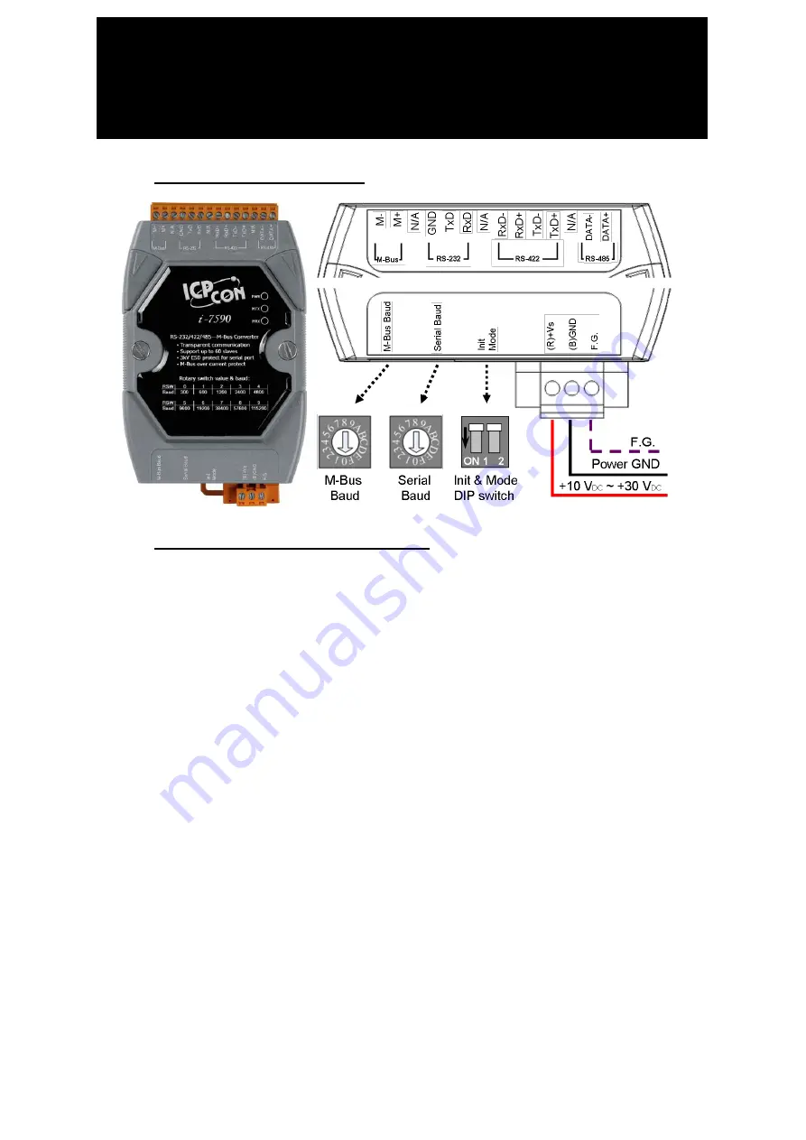
1.  Hardware Structure 


2.  Specifications & Features 


M-Bus Port: 1 


Serial Port: 1 (RS-232 / RS-422 / RS-485) 


Serial Baud and M-Bus Baud can be configured separately. 


Provides 10 kinds of Baud for default, 6 kinds of Baud for user-defined. 


Supports up to 100 M-Bus slaves. 


Provides transparent communication. 


Watchdog inside. 


Allows updating firmware by the RS-232 port. 


Overcurrent and short-circuit protection on the M-Bus port. 


3750 Vrms photocouple isolation on the M-Bus port. 


±

4 kV ESD to contact. 


Reverse polarity protection on power. 


Provide 3 LED indicators, PWR LED, MTX LED and MRX LED. 


Power requi10 V

DC

 ~ +30 V

DC


Power consumption 1.8 W @ 24 V

DC

 (with 1 slave device). 

                                    10 W @ 24 V

DC 

(with 100 slave devices). 


Operating Temperature: -25

 ~ +75

.


Storage Temperature: -30

 ~ +80

.


Humidity: 10 to 90% RH, Non-condensing. 


Dimensions: 72mm x 122mm x 33mm (W x L x H). 

I-7590 Quick Start 

RS-232/422/485 to M-Bus Convertor 

Summary of Contents for I-7590

Page 1: ...dating firmware by the RS 232 port Overcurrent and short circuit protection on the M Bus port 3750 Vrms photocouple isolation on the M Bus port 4 kV ESD to contact Reverse polarity protection on power Provide 3 LED indicators PWR LED MTX LED and MRX LED Power requirement 10 VDC 30 VDC Power consumption 1 8 W 24 VDC with 1 slave device 10 W 24 VDC with 100 slave devices Operating Temperature 25 75 ...

Page 2: ...iguration having Baud rates between 300 and 9600 Baud and a maximum of 250 slaves I 7590 supports max 100 slaves The maximum distance can be increased by limiting the Baud rate and using fewer slaves In the standard configuration the total cable length should not exceed 1000m in order to meet the requirement of a maximum cable capacitance of 180nF The number of terminals that can be connected to a...

Page 3: ... Resistor In order to stable the signals of the RS 485 and RS 422 network the bias resistor must be applied The factory default of the I 7590 is to enable the bias resistor If there is any other RS 485 or RS 422 device which has enabled the bias resistor the bias resistor of the I 7590 must be disabled Users can open the cover of the I 7590 and adjust the SW2 for RS 485 or SW2 and SW3 for RS 422 t...

Page 4: ...e configuration of the rotary switches the I 7590 needs to reboot to enable the new setting Switch Baud rate bps Format 0 300 M Bus Port 8 e 1 Serial Port 8 n 1 1 600 2 1200 3 2400 4 4800 5 9600 6 19200 7 38400 8 57600 9 115200 A F User defined User defined 6 DIP Switch The DIP switch described in the section 1 is used to update firmware and configure user defined Baud rate The configuration would...

Page 5: ...efined Baud rate and enable it by setting the rotary switches The I 7590 utility can be downloaded from the following website http ftp icpdas com tw pub cd fieldbus_cd mbus converter i 7590 software Step 1 Connect the PC COM port to the RS 232 port of the I 7590 Set the DIP switch to the configuration mode refer to the section 6 and then power it on Step 2 Execute the I 7590 utility and select the...

Page 6: ...users want to configure a new Baud rate and data format select an empty item key in the Baud rate and data format and click the Set button to finish the configuration The I 7590 supports Data Bit 5 6 7 8 Parity n e o 1 0 Stop Bit 1 2 Note Some Baud rate can t been exactly calculated as the same with the users configuration The utility would choose a closest Baud rate instead the tolerance is depen...

Page 7: ...ction please refer to the section 3 Communication Prepare a software tool which can send and receive binary commands with COM ports for example SUDT AccessPort as the following website http www sudt com en ap Send a standard M Bus command from the PC through RS 232 and I 7590 will pass the command to the M Bus network and the M Bus meter will reply the command to the PC ...

Page 8: ...the firmware The FW_Update_Tool tool can be downloaded from the ICP DAS web site http ftp icpdas com tw pub cd fieldbus_cd mbus converter i 7590 software Please follow the steps to accomplish the firmware update of the I 7590 1 Choose the correct COM port on PC that connects to the I 7590 2 Click the Browser button to choose the I 7590 firmware file such as I7590_vx xx fw 3 Click Firmware Update b...

Reviews: