background image

SERVICE AND INSTALLATION MANUAL

EF and EMF Series

Flaked ICE Machines

ICE-O-Matic
11100 East 45th Ave
Denver, Colorado 80239
Part Number 9081325-01

Print Date 1/07

Summary of Contents for EF Series

Page 1: ...SERVICE AND INSTALLATION MANUAL EF and EMF Series Flaked ICE Machines ICE O Matic 11100 East 45th Ave Denver Colorado 80239 Part Number 9081325 01 Print Date 1 07 ...

Page 2: ......

Page 3: ...eal and O Rings D2 Drip Boot D2 Drive System Auger Drive Motor and V Belt E1 Gear Reducer E2 Coupler E2 Evaporator and Internal Components E3 Evaporator Disassembly E3 Evaporator and Auger Inspection E5 Bearing Water Seal and O Rings E6 Seal Face Installation E7 Evaporator Reassembly E7 Refrigeration System Refrigeration System and Components F1 Compressor F1 Refrigerant Pressures F2 Air Cooled Co...

Page 4: ...ponent suspected of being defective A detailed description of the operation and adjustments of the components as well as other service information is laid out in the pages that follow Section C Each section after Section C focuses on a particular system in the ice machine water system drive system refrigeration system and electrical system It is important that these sections be used together with ...

Page 5: ...achine MF Modular Flake Ice Machine Serial Number Date Code The first letter in the serial number indicates the month and decade of manufacture The first digit in the serial number indicates the year of manufacture Example A0XX XXXXX Z is manufactured January 2000 A1XX XXXXX Z is manufactured January 2001 A4XX XXXXX Z is manufactured January 2004 1990 1999 MONTH 2000 2009 M JANUARY A N FEBRUARY B ...

Page 6: ......

Page 7: ...MF800A 632 287 10 5 51 115 60 1 3 19 8 20 R404A 25 709 EMF800W 756 343 9 5 51 115 60 1 3 16 5 20 R404A 16 454 EMF1106A 816 370 4 5 34 2 208 230 60 1 3 9 4 15 R404A 34 964 EMF1106W 1008 458 4 4 34 2 208 230 60 1 3 8 5 15 R404A 15 426 EMF1106R 912 414 4 5 34 2 208 230 60 1 3 10 4 15 R404A 160 4536 EMF2306A 1808 821 8 4 61 208 230 60 1 3 14 9 20 R404A 84 2382 EMF2306W 2240 1051 7 3 61 208 230 60 1 3 ...

Page 8: ...ter pressure regulator must be installed Drains Route bin drain float drain and water condenser drain individually to a floor drain The use of condensate pumps for draining water is not recommended by ICE O Matic ICE O Matic assumes no responsibility for improperly installed equipment Water Filtration A water filter system should be installed with the ice machine Clearance Requirements Self contai...

Page 9: ...Flake Ice Machines General Information Page A7 EF Series ...

Page 10: ...Flake Ice Machines General Information Page A8 EMF Series ...

Page 11: ...Flake Ice Machines General Information Page A9 EMF Series 48 Inch Wide ...

Page 12: ...ation Guidelines Ambient operating temperatures 20 F 28 9 C to 120 F 48 9 C Condenser Airflow Condensers must have a vertical airflow ICE Machine Model Number Remote Condenser Model Number EMF1106R2 VRC1061 EMF2306R2 VRC2061 Limitations for new remote machines that have the headmaster mounted in the condenser Maximum Rise is 35 feet Maximum Drop is 15 feet Page Airflow Maximum equivalent run is 10...

Page 13: ...rges related to the replacement of non defective parts or components damage by fire flood or acts of God This warranty is valid only when installation service and preventive maintenance are performed by a Company authorized distributor a Company authorized service agency or a Company Regional Manager The Company reserves the right to refuse claims made for ice machines or bins used in more than on...

Page 14: ...er level When the ON OFF switch is turned on or when the bin control closes the auger motor energizes The compressor is delayed for 2 to 4 minutes After the compressor delay period the condenser fan motor air cooled machines only and compressor start and the temperature of the evaporator barrel drops The water in the evaporator freezes to the inner walls of the evaporator barrel A belt driven gear...

Page 15: ...ditions may require that cleaning be performed more often than 6 month intervals 2 Check the water level in the float tank as described on Page D1 3 Clean the condenser air cooled machines to insure unobstructed airflow 4 Check for leaks of any kind water refrigerant oil etc 5 Check the Primary Bin Control for proper adjustment as described on Page G3 6 Check the Secondary Bin Control for proper a...

Page 16: ...are 1 gallon 3 75l of approved U S FDA 21 CFR 178 1010 food equipment sanitizer to form a solution with 100 200 ppm free chlorine yield Reserve about 1 3 gallon for step 14 below 8 Turn the machine on and add the sanitizer to the reservoir keeping the reservoir filled with sanitizer until 2 3 gallon is used up 9 Turn the machine off 10 Replace the float reservoir cover and turn the water supply ba...

Page 17: ...all ice is out of the evaporator s 3 Place the ON OFF switch to the OFF position 4 Disconnect the tubing between the evaporator and water float 5 Drain the water system completely 6 On water cooled machines hold the water regulating valve open by prying upward on the water valve spring with a screwdriver while using compressed air to blow all the water out of the condenser 7 Remove all of the ice ...

Page 18: ...layer on the surface of stainless steel that protects it from corrosion 3 Don t use cleaners that use chlorine or chlorides Don t use chlorine bleach or products like Comet to clean the steel Chlorides break down the passivation layer and can cause rusting 4 Rinse with clean water If chlorinated cleansers are used you must thoroughly rinse the surface with clean water and wipe dry immediately 5 Us...

Page 19: ...the answer will lead to either another question box a check box or a solution box CHECK boxes Rectangle will suggest a point to check for proper operation and will often refer you to a page in the service information sections of this manual The result of the check may lead to another box or a solution box SOLUTION boxes Triangle suggest the most likely component to cause the malfunction described ...

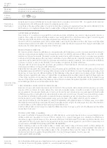
Page 20: ...Flake Ice Machines Troubleshooting Trees Page C2 Machine Runs Does Not Make Ice ...

Page 21: ...Flake Ice Machines Troubleshooting Trees Page C3 Machine Runs Does Not Make Ice ...

Page 22: ...Flake Ice Machines Troubleshooting Trees Page C4 Machine Does Not Run ...

Page 23: ...Flake Ice Machines Troubleshooting Trees Page C5 Slow Production ...

Page 24: ...Flake Ice Machines Troubleshooting Trees Page C6 Low Production ...

Page 25: ...Flake Ice Machines Troubleshooting Trees Page C7 High Suction Pressure ...

Page 26: ...Flake Ice Machines Troubleshooting Trees Page C8 Machine Freezes Up Auger Seizes ...

Page 27: ...Flake Ice Machines Troubleshooting Trees Page C9 Auger Motor Amp Draw Fluctuates ...

Page 28: ...Flake Ice Machines Troubleshooting Trees Page C10 Water Leaking From Bottom of Evaporator ...

Page 29: ...Flake Ice Machines Troubleshooting Trees Page C11 Machine Produces Wet Ice ...

Page 30: ...Flake Ice Machines Troubleshooting Trees Page C12 Hot Evaporator Low Suction Pressure and Discharge Pressure Remotes Only ...

Page 31: ...Flake Ice Machines Troubleshooting Trees Page C13 Noise Coming from Evaporator ...

Page 32: ...ball While the machine is making ice the float valve should maintain the water level so that is inch below the top insulation surrounding the evaporator barrel The water in the evaporator will also be at this level It is important that the water be maintained at this level for proper operation of the machine If the water level is too high water at the top of the evaporator will not freeze and wet ...

Page 33: ... seal face If the water seal fails water will usually leak between the lower bearing and the auger shaft See Page E6 for water seal replacement procedure Note The water seal is available only as a complete assembly Both seal and seal face must be replaced together Lower Housing Seal O Ring Lower bearing Seal Face Drip Boot The drip boot is located at the bottom of the evaporator to catch condensat...

Page 34: ...ing a straight edge across the face of the two pulleys If out of alignment the pulleys can be repositioned by loosening the setscrew that holds the pulley to the shaft realign the pulleys and then retighten the setscrew The V Belt can be adjusted by loosening the four 4 auger motor mounting bolts and moving the motor until the proper belt tension is achieved The belt should be adjusted so that it ...

Page 35: ...ed Mounting Bracket Output Shaft If the gear reducer is damaged it may bind or lock up causing the auger motor to shut off on overload This is usually caused by a damaged worm gear due to lack of lubricant or excessive loading of the gear reducer Input Shaft Note The are no serviceable parts available for the gear reducer The 9171010 03 Gear Reducer is a sealed component and does not require servi...

Page 36: ...cap insulation and ice chute from the top of the evaporator On EF models remove the top panel and disconnect the wires from the secondary bin control and remove the bin control cap tube from the brass tube Drain the evaporator by disconnecting the water feed tube from the float to the evaporator On EF models remove the chassis from the cabinet by disconnecting the water and drain lines and the inc...

Page 37: ... shaft will result Upper Nut Right Hand Thread Remove the seal face from the auger by prying it off with a screwdriver Remove the lower evaporator retaining nut by first using an 1 8 inch Allen wrench to remove the two 2 inch set screws from the lower nut Remove the lower evaporator retaining nut by using a chain wrench wrap chain around the lower part of the nut to loosen the nut Right Hand Threa...

Page 38: ...an the auger and inspect for corrosion or wear If the auger is corroded or if the flights are worn from contact with the evaporator walls it should be replaced If the evaporator wall is scored by the auger the evaporator will need to be replaced The auger bearing journals can be checked for wear by using hand pressure to install a new bearing onto the journals The bearing should fit tightly around...

Page 39: ...t housing on housing flange Remove the O Rings and clean the upper and lower bearing housings Housings Shown Inverted Install the new upper bearing race and lower bearing in their respective housings with a bearing press or a bearing driver Do not use a hammer directly in the bearing or bearing race Bearing Install new O Rings in the upper and lower housings lightly lubricate the O Rings with whit...

Page 40: ...plying even pressure upward It may be necessary to tap the housing with a rubber mallet or with a hammer and hard wooden block Install and tighten the lower evaporator nut Install and tighten the lower nut setscrews Carefully install the auger and upper housing assembly into the evaporator barrel taking care not to scrape the evaporator walls Push downward on the housing until the bearing housing ...

Page 41: ...Flake Ice Machines Drive System Page E8 Exploded View of the Evaporator ...

Page 42: ...ed whenever the refrigeration system is opened or if the refrigerant charge is lost Compressor The compressor runs during the entire ice making cycle If the valves in the compressor are damaged the compressor will be unable to pump refrigerant efficiently Damaged valves may be the symptom of another problem in the refrigeration system such as liquid returning to the compressor or high head pressur...

Page 43: ......

Page 44: ...ber Temp F Temp F Pressure PSIG 192 LAC 240 LAC EMF2306R 90 F 70 F 40 265 266 70 F 50 F 35 217 260 20 F 50 F 40 F 33 200 263 120 F 110 F 100 F 45 365 355 EMF2306W 90 F 70 F 38 250 70 F 50 F 37 250 50 F 40 F 36 250 110 F 100 F 42 250 EMF405A 90 F 70 F 56 274 70 F 50 F 53 215 50 F 40 F 36 158 110 F 100 F 61 352 EMF450A 90 F 70 F 56 290 70 F 50 F 52 222 50 F 40 F 51 131 110 F 100 F 57 374 EMF450W 90 ...

Page 45: ...5A 70 F 50 F 50 53 225 90 F 70 F 54 57 285 290 EF EMF450A 70 F 50 F 49 53 260 90 F 70 F 53 57 320 325 EMF450W 70 F 50 F 50 52 250 90 F 70 F 52 53 250 EMF705A 70 F 50 F 38 40 270 90 F 70 F 42 45 345 350 EF EMF800A 70 F 50 F 45 48 275 90 F 70 F 49 51 340 345 EMF800W 70 F 50 F 41 43 250 90 F 70 F 41 43 250 EMF1005A 70 F 50 F 38 42 295 300 90 F 70 F 42 45 328 333 EMF1106A 70 F 50 F 41 43 270 90 F 70 F...

Page 46: ......

Page 47: ... of failure due to excessive mineral build up will not be covered under warranty Water Regulating Valve The water regulating valve controls the head pressure by regulating the amount of water flow through the condenser The bellows of the water regulating valve are connected to the high side of the refrigeration system As the discharge pressure rises the bellows expand increasing the water flow thr...

Page 48: ... than normal Wet ice or slow production will result A low refrigerant charge will also starve the evaporator and cause low suction and discharge pressure It is important that the refrigerant charge be correct before diagnosing the valve If not sure of the amount of charge in the system the refrigerant should be recovered and the correct charge weighed in If the evaporator is starved but the suctio...

Page 49: ...vercharged d An expansion valve stuck open a TXV restricted or sticking closed Problem a Clean suction line and clamp bulb securely Insulate bulb b Relocate sensing bulb to top of suction line c Recover refrigerant and weigh in correct charge d Replace TXV a Recover refrigerant and weigh in correct charge b Replace TXV and filter drier a Recover refrigerant and weigh in proper charge b Replace TXV...

Page 50: ...ction pressure is higher than normal and ice production is slow it is possible that the evaporator has coil separation Evaporator coil separation is the separation of the refrigerant tubing from the evaporator barrel This is rare but may occur from time to time Usually all of the following symptoms will be present Higher than normal suction pressure Cold or frosted compressor suction line Slow ice...

Page 51: ...s If the condenser fins are bent this will restrict the airflow through the condenser and the fins will need to be straightened with a fin comb Problems related to a dirty condenser or poor airflow will not be covered under warranty Note The condenser fan motor runs continually it will shut off when the icemaker shuts off Air Flow Mixing Valve L A C Headmaster When the temperature at the condenser...

Page 52: ...let of the receiver is de energized causing the valve to close completely restricting the flow of refrigerant The compressor will pump all of the refrigerant into the condenser and receiver As the system pumps down the pressure on the low side of the system drops When the suction pressure drops to 19 psi 1 3 bar the pump down control opens and shuts the machine off See page G5 for pump down contro...

Page 53: ...mperature and pressure of the vapor are increased The high temperature high pressure vapor flows to the condenser where the heat is removed causing the vapor to return to the liquid form making the refrigerant ready to flow back to the evaporator to pick up more heat Most Ice O Matic ice machine use R134a or R404a refrigerant Always check the serial number data plate for the proper type of refrige...

Page 54: ...ates a dry system under a good vacuum If your gauge registers a more rapid rise the system either has moisture remaining or there is a leak in the system requiring a check for the leak and repair and another complete evacuation Note Seal the ends of the gauge manifold hose and pull them into a deep vacuum to determine if the leak is not in the hoses The gauge manifold should be able to hold the va...

Page 55: ...n some cases the complete refrigerant charge may not enter the refrigeration system In those instances close the gauge manifold high side valve and disconnect the manifold from the high side port When the icemaker is completely charged secure the caps to the service ports and check to make sure the ports are not leaking refrigerant Reference Tables on Page A5 ...

Page 56: ...is energizes the compressor start components which starts the compressor Compressor and Start Components The compressor should run during the entire cycle If the machine is in the ICE position but the compressor is not running check the compressor contactor to see if it is engaged If the contactor is not engaged the problem is not with the compressor or the compressor start components If the conta...

Page 57: ... not be covered under the warranty policy if they are not defective Overload External If there is no amperage draw check the compressor overload The compressor overload can be checked for continuity after removing it from the compressor and letting it cool to room temperature If there is no continuity between the two terminals replace the overload If the overload is suspected of opening prematurel...

Page 58: ... the adjusting screw clockwise to lower the cut out temperature colder and counterclockwise to raise the cut out temperature warmer Bin Control A primary thermostatic bin control and mechanical secondary bin switch in used to shut the machine off when the bin becomes full of ice Adjustment Screw Thermostatic Bin Control The thermostatic bin control is located in the control box with the capillary ...

Page 59: ...Relay The auger motor relay is used on modular models to energize the auger motor preventing excessive current through the bin control When power is supplied to the coil of the relay the normally open contacts close energizing the auger motor Auger Motor The auger drive motor is used to turn the gear reducer via a V Belt The auger motor should turn counter clockwise when facing the pulley end of t...

Page 60: ... close This blocks the flow of refrigerant causing all the refrigerant to be pumped into the receiver and condenser This is done to prevent liquid refrigerant from migrating into the compressor during the off cycle which could damage the compressor on start up Also see Pump Down System in the Refrigeration Section on page F11 As the refrigerant is pumped into the receiver the suction pressure begi...

Page 61: ...Flake Ice Machines Electrical System Page G6 9071694 01 EF250 255 405 EF450A W ...

Page 62: ...Flake Ice Machines Electrical System Page G7 9071963 01 EF800A W ...

Page 63: ...Flake Ice Machines Electrical System Page G8 EMF450 405A W 9071958 01 ...

Page 64: ...Flake Ice Machines Electrical System G9 Page 9071954 01 EMF800A W ...

Page 65: ...Flake Ice Machines Electrical System Page G10 9071956 01 EMF705 1005 1006A W ...

Page 66: ...Flake Ice Machines Electrical System Page G11 9071962 01 EMF1106R ...

Page 67: ...Flake Ice Machines Electrical System Page G12 9071955 01 EMF2306A W ...

Page 68: ...Flake Ice Machines Electrical System Page G13 9071960 01 EMF2306R ...

Page 69: ...Flake Ice Machines Electrical System Page G14 9071959 01 EMF2305L ...

Page 70: ......

Page 71: ......

Page 72: ......

Reviews: