background image

Welcome.

This
contains information for setting
up and configuring your BladeCenter
unit and its components.

For additional information about
your BladeCenter device view
the publications on the

You can

also find the most
current information about
BladeCenter devices at
http://www.ibm.com/support/.

Installation and User's Guide

Documentation CD.

Installation and User's
Guide

BladeCenter H

Types 8852, 7989, and 1886

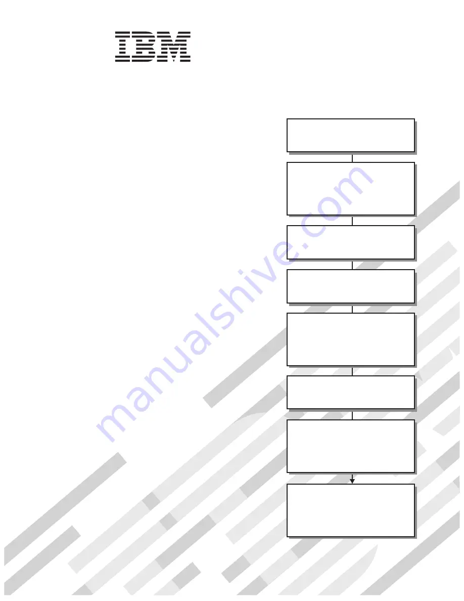
Read the BladeCenter overview in

Chapter 1 of this

.

Installation and User's Guide

Define and document the configuration

parameters for your BladeCenter unit

using the worksheets in Appendix A of this

.

Installation and User's Guide

Set up your operating environment and

install the rack using the

instructions that come with the rack.

Install the BladeCenter unit in the rack

using the instructions in this

.

Installation and

User's Guide

Install the power modules and

management modules in the BladeCenter

unit using the instructions in this

and the documents

that come with each component.

Installation

and User's Guide

Perform initial BladeCenter unit

configuration using the instructions in the

Management Module User's Guide.

Install and configure I/O modules in the

BladeCenter unit using the instructions in

this

and the documents that come

with each I/O module.

Installation and User's Guide

Install and configure blade servers in the

BladeCenter unit using the instructions in

this

and the documents that come

with each blade server.

Installation and User's Guide

Summary of Contents for 8852 - BladeCenter H Rack-mountable

Page 1: ...e Set up your operating environment and install the rack using the instructions that come with the rack Install the BladeCenter unit in the rack using the instructions in this Installation and User s...

Page 2: ......

Page 3: ...BladeCenter H Type 8852 7989 and 1886 Installation and User s Guide...

Page 4: ...mation in Appendix B Getting help and technical assistance on page 51 and Appendix C Notices on page 53 Fifth Edition September 2010 Copyright IBM Corporation 2010 US Government Users Restricted Right...

Page 5: ...12 Front view 12 Power modules 12 Media tray 13 System service cards 14 Blade server control panel 14 Rear view 15 Power connectors 15 I O modules 15 Management modules 15 Blower modules 15 Serial con...

Page 6: ...Getting help and technical assistance 51 Before you call 51 Using the documentation 51 Getting help and information from the World Wide Web 51 Software service and support 52 Hardware service and sup...

Page 7: ...ndustries Association JEITA statement 58 Korea Communications Commission KCC statement 58 Russia Electromagnetic Interference EMI Class A statement 58 People s Republic of China Class A electronic emi...

Page 8: ...vi BladeCenter H Type 8852 7989 and 1886 Installation and User s Guide...

Page 9: ...lleert eerst de veiligheidsvoorschriften Ennen kuin asennat t m n tuotteen lue turvaohjeet kohdasta Safety Information Avant d installer ce produit lisez les consignes de s curit Vor der Installation...

Page 10: ...ed versions of the caution or danger statement in the Safety Information document For example if a caution statement is labeled Statement 1 translations for that caution are in the Safety Information...

Page 11: ...quipment when there is evidence of fire water or structural damage v Disconnect the attached power cords telecommunications systems networks and modems before you open the device covers unless instruc...

Page 12: ...rives fiber optic devices or transmitters are installed note the following v Do not remove the covers Removing the covers of the laser product could result in exposure to hazardous laser radiation The...

Page 13: ...wer control button on the device and the power switch on the power supply do not turn off the electrical current supplied to the device The device also might have more than one power cord To remove al...

Page 14: ...parts contact a service technician Statement 12 CAUTION The following label indicates a hot surface nearby Statement 13 DANGER Overloading a branch circuit is potentially a fire hazard and a shock ha...

Page 15: ...tatement 21 CAUTION Hazardous energy is present when the blade is connected to the power source Always replace the blade cover before installing the blade United Kingdom Notice to Customers This appar...

Page 16: ...xiv BladeCenter H Type 8852 7989 and 1886 Installation and User s Guide...

Page 17: ...ers that provide cooling for most BladeCenter components There are two blower modules v There are three fans attached to each power module that provide cooling for the power modules and other componen...

Page 18: ...number _____________________________________________ The serial number and model number are on labels on the top front and rear of the chassis A set of blank labels comes with each blade server Recor...

Page 19: ...nit on Altitude 0 to 914 m 3000 ft 10 to 35 C 50 to 95 F Altitude 914 m to 2134 m 3000 ft to 7000 ft 10 to 32 C 50 to 90 F BladeCenter unit off 40 to 60 C 40 to 140 F v Humidity 8 to 80 v Acoustics de...

Page 20: ...he same type Switch modules which provide a communication link for the third and fourth NICs in each blade server The modules in these bays must support the type of network interface that is used in t...

Page 21: ...as required to control internal BladeCenter unit temperature If a blower fails the operating speed of the remaining blower might increase and continue to cool the BladeCenter unit and blade servers Re...

Page 22: ...of the document appears under Topic Description To select more than one document press and hold the Ctrl key while you select the documents Click View Book to view the selected document or documents...

Page 23: ...tion to help you solve problems and it contains information for service technicians v BladeCenter Advanced Management Module Installation Guide This document contains instructions for installing the m...

Page 24: ...inconvenient or problem situations v Attention These notices indicate possible damage to programs devices or data An attention notice is placed just before the instruction or situation in which damag...

Page 25: ...Blade Server Control Panel Secondary CD See hardware for actual location of LEDs and buttons See hardware for actual location of LEDs and buttons DC OK BladeCenter Service Information I O module I O...

Page 26: ...10 BladeCenter H Type 8852 7989 and 1886 Installation and User s Guide...

Page 27: ...it from the power source To disconnect power from the BladeCenter unit complete the following steps 1 Shut down each blade server See the documentation that comes with your blade servers for the proce...

Page 28: ...rror LED AC power LED DC power LED The LEDs on each power module indicate the condition of the power module and fan pack Note The orientation of the power module shown in the illustration is for one o...

Page 29: ...the BladeCenter unit Location When this blue LED is lit or flashing it has been turned on by the system administrator to aid in visually locating the BladeCenter unit If a blade server requires atten...

Page 30: ...Press this button to release a disc from the optical drive v USB connectors Use these connectors to attach USB devices System service cards These cards contain system service instructions and a writab...

Page 31: ...tion of the LEDs and connectors on the I O module Management modules See the documentation that comes with each management module for a description of the LEDs and connectors on the module Blower modu...

Page 32: ...16 BladeCenter H Type 8852 7989 and 1886 Installation and User s Guide...

Page 33: ...BladeCenter unit into the rack See the BladeCenter H Rack Installation Instructions __ 5 Reinstall the removed modules in the BladeCenter unit Make sure that the BladeCenter unit has adequate power t...

Page 34: ...ibm com bladecenter System reliability guidelines To help ensure proper cooling and system reliability make sure that the following requirements are met v Each of the module bays on the rear of the B...

Page 35: ...c electricity Removing components before rack installation Attention See the BladeCenter H Problem Determination and Service Guide for removing components from the BladeCenter unit when the unit is co...

Page 36: ...upper power module bays push the inner handle release to the right then pull the handle up to the open position v For a power module in one of the lower power module bays push the inner handle release...

Page 37: ...on page 18 2 Move the two release handles to the open position The blade server moves out of the bay approximately 0 6 cm 0 25 inch 3 Pull the blade server out of the bay Removing a management module...

Page 38: ...d Installation guidelines on page 18 2 Press the release button on the blower handle and rotate the handle to the open position rotate to the right for the upper blower module or to the left for the l...

Page 39: ...of the bay Removing a bezel When working with some devices such as the media tray and power modules you must first remove the top or bottom bezels to access the devices To remove either bezel complete...

Page 40: ...circuit board or any of its components 5 Press the optical drive filler retainer tab and slide the optical drive filler out of the media tray 6 Remove the retainer clip from the side of the optical d...

Page 41: ...depends on a variety of additional factors including the duration of employees exposure and whether employees wear hearing protection It is recommended that you consult qualified experts in this fiel...

Page 42: ...e is in the open position 3 Slide the module into the module bay until it stops 4 Push the release handle on the module to the closed position 5 Connect any cables to the module 6 If the BladeCenter u...

Page 43: ...s I O module Module filler I O module Single module filler Double module filler Release handles open Release handle open 1 Remove the module filler if one is installed 2 Make sure that the release han...

Page 44: ...ade slots 1 to 7 v Power modules 3 and 4 provide power for domain B blade slots 8 to 14 The following is an example of a supported configuration v Domain A Power Module 1 2900W Power Module 2 2900W v...

Page 45: ...odule bays the rear connector on the power module must be facing down v For the lower power module bays the rear connector on the power module must be facing up 4 Slide the module into the bay until i...

Page 46: ...he circuit board facing up Attention To prevent damage to the circuit board do not touch or apply pressure to the circuit board or any of its components 3 Install the retainer clip on the side of the...

Page 47: ...1 CAUTION Hazardous energy is present when the blade is connected to the power source Always replace the blade cover before installing the blade Attention If this is the initial installation of a blad...

Page 48: ...this is a new blade server write identifying information on one of the user labels that come with the blade server then place the label on the BladeCenter unit top bezel just above the blade server Im...

Page 49: ...d indicators on page 11 for information about the location of the LEDs on the modules See the documentation that comes with the blade servers for the location of the LEDs on the blade servers Chapter...

Page 50: ...34 BladeCenter H Type 8852 7989 and 1886 Installation and User s Guide...

Page 51: ...nagement module uses the static IP address Use the management module to configure other BladeCenter component settings such as user accounts DHCP or Wake on LAN See the documentation for your manageme...

Page 52: ...le bays 1 and 2 There is no internal data path between the two switches within the BladeCenter unit an external network device is required for data packets to flow from one internal switch to the othe...

Page 53: ...in PDF at http www ibm com servers eserver xseries systems_management sys_migration ibmdiragent html It is updated every 6 to 8 weeks v Support for IBM and non IBM servers desktop computers workstatio...

Page 54: ...38 BladeCenter H Type 8852 7989 and 1886 Installation and User s Guide...

Page 55: ...ner The video from blade server 14 is displayed on the monitor briefly until the management module uses its NVRAM values to reestablish ownership of the KVM and media tray optical drive diskette drive...

Page 56: ...e server must provide USB support for the blade server to recognize and use the media tray The BladeCenter unit uses USB for internal communication with these devices 40 BladeCenter H Type 8852 7989 a...

Page 57: ...system errors quickly See Light path diagnostic LEDs on page 44 Troubleshooting tables Use the troubleshooting tables to find solutions to problems that have identifiable symptoms Note The symptoms f...

Page 58: ...is turned on v The KVM is owned by a blade server that supports KVM 2 Reseat the monitor cable 3 Replace the monitor Power problems v Follow the suggested actions in the order in which they are listed...

Page 59: ...e has been installed for at least 45 minutes to receive the transfer of data from the primary management module v The network cable is connected to the Ethernet port on the active redundant management...

Page 60: ...a system of LEDs on the BladeCenter unit and the BladeCenter components that can be used to identify system errors If the front or rear system error LED of the BladeCenter unit is lit one or more erro...

Page 61: ...or temperature information 3 Determine whether a blade server has a lit error LED If it does see the documentation that comes with the blade server 4 Make sure that there is a blade server module or f...

Page 62: ...46 BladeCenter H Type 8852 7989 and 1886 Installation and User s Guide...

Page 63: ...ring the BladeCenter unit using the management module Information about using the worksheet is provided in the Management Module User s Guide for your management module General settings Management mod...

Page 64: ...onfiguration configure only if DHCP is disabled IP address ___ ___ ___ ___ Subnet mask ___ ___ ___ ___ Gateway IP address ___ ___ ___ ___ Internal network interface eth1 Interface IP address ___ ___ _...

Page 65: ...mail alerts __ Yes __ No Alerts to be monitored Critical alerts Select all critical alerts Hard disk drive Multiple blower failures Power failure Temperature VRM failure Multiple switch module failur...

Page 66: ...dress DNS DNS __ Enable __ Disable DNS server IP address 1 ___ ___ ___ ___ DNS server IP address 2 ___ ___ ___ ___ DNS server IP address 3 ___ ___ ___ ___ Security Secure Socket Layer SSL __ Enabled _...

Page 67: ...agnostic tests that you can perform Most systems operating systems and programs come with documentation that contains troubleshooting procedures and explanations of error messages and error codes If y...

Page 68: ...e U S and Canada call 1 800 IBM SERV 1 800 426 7378 Hardware service and support You can receive hardware service through your IBM reseller or IBM Services To locate a reseller authorized by IBM to pr...

Page 69: ...s or implied warranties in certain transactions therefore this statement may not apply to you This information could include technical inaccuracies or typographical errors Changes are periodically mad...

Page 70: ...DVD drive speed is the variable read rate Actual speeds vary and are often less than the possible maximum When referring to processor storage real and virtual storage or channel volume KB stands for...

Page 71: ...such remedial measures is a customer responsibility Table 2 Limits for particulates and gases Contaminant Limits Particulate v The room air must be continuously filtered with 40 atmospheric dust spot...

Page 72: ...by using other than recommended cables and connectors or by unauthorized changes or modifications to this equipment Unauthorized changes or modifications could void the user s authority to operate the...

Page 73: ...wortung f r die Einhaltung der Schutzanforderungen wenn das Produkt ohne Zustimmung der IBM ver ndert bzw wenn Erweiterungskomponenten von Fremdherstellern ohne Empfehlung der IBM gesteckt eingebaut w...

Page 74: ...interference may occur in which case the user may be required to take corrective actions Japan Electronics and Information Technology Industries Association JEITA statement Japanese Electronics and In...

Page 75: ...People s Republic of China Class A electronic emission statement Taiwan Class A compliance statement Appendix C Notices 59...

Page 76: ...60 BladeCenter H Type 8852 7989 and 1886 Installation and User s Guide...

Page 77: ...onfiguring the management module 35 connector Universal Serial Bus 14 connectors front 12 contamination particulate and gaseous 55 controls 12 front 12 cooling 3 D description blade server 4 BladeCent...

Page 78: ...ttings 47 installing 26 internal network interface 48 login profiles 47 network protocols 50 problems 43 removing 21 security 50 media tray problems 44 module blower 5 module continued management 4 po...

Page 79: ...bility 18 system specifications 3 systems management 37 T telephone numbers 52 trademarks 53 troubleshooting 41 charts 41 U United States electronic emission Class A notice 56 United States FCC Class...

Page 80: ...64 BladeCenter H Type 8852 7989 and 1886 Installation and User s Guide...

Page 81: ......

Page 82: ...Part Number 81Y1106 Printed in USA 1P P N 81Y1106...

Reviews: