background image

Welcome. . .

Thank you for buying an
IBM xSeries server.

This server
contains information for setting
up and configuring your server.

For detailed information about
your server, view the publications
on the

You can also find the most
current information about your
server on the IBM Web site at:
http://www.ibm.com/pc/support

Your server

is based on the X-Architecture
technology, and it features
superior performance, availability,
and scalability.

Documentation CD.

Installation Guide

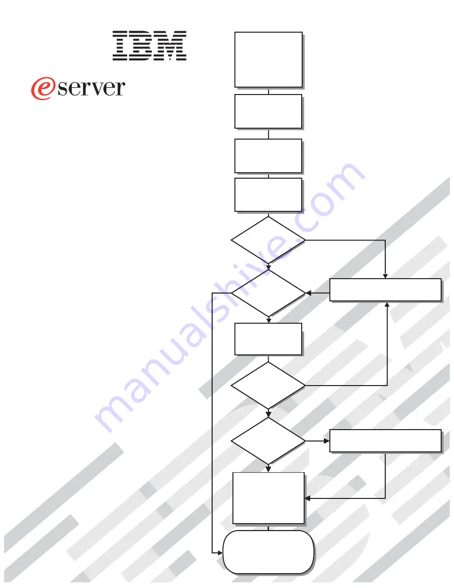
Go to the Server Support

flow chart

Cable the server

and options

Start the server

Install options,
if required
• Drives
• Microprocessors
• Adapters
• Memory

Did the server

start correctly?

Yes

No

Use ServerGuide to

set up and

configure hardware

Did configuration

complete?

Is the Server

preconfigured?

Use

ServerGuide to

install operating

system?

Install applications,
such as IBM systems
management software
and IBM ServeRAID
programs

System is ready to use.

Go to the Server Support

flow chart to register

and profile your server.

Go to the Web for instructions,
http://www.ibm.com/pc/support

No

Yes

Yes

Yes

No

No

Installation Guide

Install the server in

the rack cabinet,

if required

xSeries 445

Type 8870

Summary of Contents for eServer 445 xSeries

Page 1: ...e Server Support flow chart Cable the server and options Start the server Install options if required Drives Microprocessors Adapters Memory Did the server start correctly Yes No Use ServerGuide to set up and configure hardware Did configuration complete Is the Server preconfigured Use ServerGuide to install operating system Install applications such as IBM systems management software and IBM Serv...

Page 2: ...or loose connections and verify that all optional devices you installed are on the ServerProven list You can view the ServerProven list at http www ibm com pc compat Server working properly Problem solved Problem solved Hardware or software problem View support telephone numbers at http www ibm com planetwide View information about IBM support line at or view support telephone numbers at http www ...

Page 3: ...xSeries 445 Type 8870 Installation Guide ERserver ...

Page 4: ... page 81 Appendix B IBM Statement of Limited Warranty Z125 4753 07 11 2002 on page 83 and Appendix C Notices on page 99 Second Edition January 2004 Copyright International Business Machines Corporation 2004 All rights reserved US Government Users Restricted Rights Use duplication or disclosure restricted by GSA ADP Schedule Contract with IBM Corp ...

Page 5: ...ng a ServeRAID adapter 29 Installing the serial port 31 Completing the installation 33 Installing the server in the rack cabinet 33 Connecting the cables 34 Power cabling 48 SCSI cabling 48 USB cabling 48 Video cabling 48 Mouse cabling 48 Keyboard cabling 49 Gigabit Ethernet cabling 49 Remote Supervisor Adapter cabling 49 Chapter 3 Server controls LEDs and power 51 Front view 51 Rear view 53 Serve...

Page 6: ...tement of Limited Warranty Z125 4753 07 11 2002 83 Part 1 General Terms 83 Part 2 Country unique Terms 86 Part 3 Warranty Information 97 Appendix C Notices 99 Edition notice 99 Trademarks 100 Important notes 101 Product recycling and disposal 101 Battery return program 102 Electronic emission notices 102 Federal Communications Commission FCC statement 102 Industry Canada Class A emission complianc...

Page 7: ...talleert eerst de veiligheidsvoorschriften Ennen kuin asennat tämän tuotteen lue turvaohjeet kohdasta Safety Information Avant d installer ce produit lisez les consignes de sécurité Vor der Installation dieses Produkts die Sicherheitshinweise lesen Prima di installare questo prodotto leggere le Informazioni sulla Sicurezza Les sikkerhetsinformasjonen Safety Information før du installerer dette pro...

Page 8: ...or disconnect signal cables v Never turn on any equipment when there is evidence of fire water or structural damage v Disconnect the attached power cords telecommunications systems networks and modems before you open the device covers unless instructed otherwise in the installation and configuration procedures v Connect and disconnect cables as described in the following table when installing movi...

Page 9: ...ces or regulations Statement 3 CAUTION When laser products such as CD ROMs DVD drives fiber optic devices or transmitters are installed note the following v Do not remove the covers Removing the covers of the laser product could result in exposure to hazardous laser radiation There are no serviceable parts inside the device v Use of controls or adjustments or performance of procedures other than t...

Page 10: ...ton on the device and the power switch on the power supply do not turn off the electrical current supplied to the device The device also might have more than one power cord To remove all electrical current from the device ensure that all power cords are disconnected from the power source 1 2 viii xSeries 445 Type 8870 Installation Guide ...

Page 11: ...f these parts contact a service technician Statement 10 CAUTION Do not place any object weighing more than 82 kg 180 lb on top of rack mounted devices 82 kg 180 lb Statement 13 DANGER Overloading a branch circuit is potentially a fire hazard and a shock hazard under certain conditions To avoid these hazards ensure that your system electrical requirements do not exceed branch circuit protection req...

Page 12: ...h hands after handling ADVERTENCIA El contacto con el cable de este producto o con cables de accesorios que se venden junto con este producto pueden exponerle al plomo un elemento químico que en el estado de California de los Estados Unidos está considerado como un causante de cancer y de defectos congénitos además de otros riesgos reproductivos Lávese las manos después de usar el producto x xSeri...

Page 13: ...p www ibm com pc support 2 In the Learn section click Online publications 3 On the Online publications page in the Brand field select Servers 4 In the Family field select xSeries 445 5 Click Continue Your server comes with an IBM ServerGuide Setup and Installation CD to help you configure the hardware install device drivers and install the operating system Your server comes with a limited warranty...

Page 14: ...iptions of the books and view books using Adobe Acrobat Reader or xpdf The Documentation Browser automatically detects the regional settings in use in your system and displays the books in the language for that region if available If a book is not available in the language for that region the English version is displayed Use one of the following procedures to start the Documentation Browser v If A...

Page 15: ... it and press Crtl F to use the Acrobat search function or Alt F to use the xpdf search function within the book Click Help for detailed information about using the Documentation Browser Notices and statements used in this publication The caution and danger statements that appear in this publication are also in the multilingual Safety Information publication which is on the IBM xSeries Documentati...

Page 16: ...on Integrated functions v Broadcom 5704 Dual Gigabit 10 100 1000 Ethernet controller v Light path diagnostics feature v LSI Logic 1030 Dual Ultra320 SCSI controller v Remote Supervisor Adapter II EXA ATI Radeon RV 100 video controller Ethernet port RSA II EXA breakout port v Remote Supervisor Adapter ASM interconnect port Ethernet port Management port v IDE controller v RXE Management Port v Three...

Page 17: ...ts of the xSeries 445 server The following illustration shows the locations of major components in your server Note The illustrations in this document might differ slightly from your hardware Chapter 1 Introduction 5 ...

Page 18: ...O X EMC shield for single SMP Expansion Module SMP baffle Retention bracket SMP Expansion Module DIMM Heat sink Microprocessor Microprocessor baffle Fan 4 Hard disk drive DVD ROM drive VRM Cover Thumbscrews DIMM access doors Fan 3 Fan 1 Fan 2 Hot swap power supply Bezel Shipping thumbscrews Center plane Figure 2 Major components of the xSeries 445 server 6 xSeries 445 Type 8870 Installation Guide ...

Page 19: ...system support hot swap capability you can remove or install the component while the server is running Orange can also indicate touch points on hot swap components See the instructions for removing or installing a specific hot swap component for any additional procedures that you might have to perform before you remove or install the component v For a list of supported options for your server go t...

Page 20: ...amage keep static sensitive devices in their static protective packages until you are ready to install them To reduce the possibility of damage from electrostatic discharge observe the following precautions v Limit your movement Movement can cause static electricity to build up around you v Handle the device carefully holding it by its edges or its frame v Do not touch solder joints pins or expose...

Page 21: ...nstructions for removing and installing the SMP Expansion Module microprocessors VRMs and DIMMs The following notes describe components in the SMP Expansion Module and other information that you must consider when installing an SMP Expansion Module v Use two hands to install or remove an SMP Expansion Module Do not allow the expansion module to come in contact with the center plane while lifting i...

Page 22: ...ing or installing SMP Expansion Modules you must remove the retention bracket or brackets and electromagnetic compatibility EMC shield from the rear of the server v You must run the Configuration Setup Utility program whenever you remove or replace an SMP Expansion Module or one of its associated options Locking levers CAM opening Figure 4 Complete SMP Expansion Module 10 xSeries 445 Type 8870 Ins...

Page 23: ...s from the right side of the server Note There are two shipping thumbscrews per retention bracket b Grasp the retention bracket by the removal handles and lift it up and out of the server Store the retention bracket or brackets in a safe place for later use Note If there is one SMP Expansion Module installed you will need to remove the SMP baffle from the server then remove the retention bracket f...

Page 24: ...on the top of the SMP Expansion Modules and lift them up slightly For use with one SMP Module For use with two SMP Modules EMC shields Thumbscrews Thumbscrews Figure 6 EMC shields N O T E F O R P R O P E R A IR F L O W R E P L A C E F A N W IT H IN 2 M IN U T E S F R O N T O F B O X N O T E F O R P R O P E R A IR F L O W R E P L A C E F A N W IT H IN 2 M IN U T E S F R O N T O F B O X EMC Shield S...

Page 25: ...Rotate the two locking levers until they are fully extended beyond the edge of the SMP Expansion Module cover Do not force the locking levers past the position shown in the illustration N O T E F O R P R O P E R A IR F L O W R E P L A C E F A N W IT H IN 2 M IN U T E S F R O N T O F B O X N O T E F O R P R O P E R A IR F L O W R E P L A C E F A N W IT H IN 2 M IN U T E S F R O N T O F B O X Latch ...

Page 26: ...ront edge of the cover off the SMP Expansion Module d Lift the cover off the SMP Expansion Module Figure 10 Lifting the front of the cover Figure 11 Lifting the cover off the SMP Expansion Module 14 xSeries 445 Type 8870 Installation Guide ...

Page 27: ...on the World Wide Web v The microprocessor in socket 1 of the bottom SMP Expansion Module is the startup boot microprocessor v An air baffle or microprocessor must be installed in microprocessor socket 4 depending on your configuration v If you are adding Intel Xeon MP microprocessors populate the empty microprocessor sockets in numeric order starting with socket 1 If you install the microprocesso...

Page 28: ...n to install the microprocessor then remove the module cover and determine the socket where the microprocessor is to be installed For details see Removing an SMP Expansion Module and cover on page 11 5 Determine which type of microprocessors are installed in your server The easiest way to do this is by the locations of the installed microprocessors in the SMP Expansion Module If the microprocessor...

Page 29: ... Attention You must ensure that the locking lever on the microprocessor socket is in the fully open position before you insert the microprocessor in the socket Failure to do so might result in permanent damage to the microprocessor microprocessor socket and SMP expansion board c Align the triangle icon on the microprocessor with the triangle icon on the socket and press the microprocessor gently i...

Page 30: ... the bottom of the new heat sink Doing so damages its heat conducting capability and exposes the new microprocessor to overheating b Align the heat sink over the microprocessor then carefully set it down on top of the microprocessor Figure 14 Microprocessor VRM Captive screws Heat sink Protective cover Figure 15 Placing the heat sink on the microprocessor 18 xSeries 445 Type 8870 Installation Guid...

Page 31: ... the VRM is properly seated in the slot Installing a memory module The following notes describe the types of dual inline memory modules DIMMs that your server supports and other information that you must consider when installing DIMMs v IBM periodically makes updates available to provide enhancements to the standard features of your server Currently your server supports the memory mirroring and Me...

Page 32: ...nfiguration Setup Utility program to save the new configuration information Start the Configuration Setup Utility program and select Save Settings See the User s Guide on the IBM xSeries Documentation CD for additional information v You can configure your server to use memory mirroring and memory scrubbing For detailed information about configuring your server and using these features see the User...

Page 33: ... 11 for instructions 4 Open the DIMM access door on the SMP Expansion Module cover that covers the memory port in which you will be installing the new DIMMs Note The illustrations in this document might differ slightly from your hardware Attention When you handle static sensitive devices take precautions to avoid damage from static electricity For details on handling these devices see Handling sta...

Page 34: ... not been properly installed In this case open the retaining clips and remove the DIMM then reinsert the DIMM 7 Close the DIMM access door or reinstall the SMP Expansion Module cover see Reinstalling an SMP Expansion Module and cover on page 23 8 If you have other options to install or remove do so now 9 Close the server cover then go to Completing the installation on page 33 Note When you restart...

Page 35: ...on the SMP Expansion Module a Set the cover on top of the expansion module b Extend the locking levers as shown in the illustration then let the cam on the front of the cover fall into the cam opening on the SMP Expansion Module circuit board c Release the locking levers and align the rear of the cover with the rear edge of the circuit board d Press down on the cover until it snaps into place Lock...

Page 36: ...r plane lower the SMP Expansion Module into the server c Release the handle and slide the SMP Expansion Module toward the center plane until it stops Locking levers Handle Figure 20 Locking lever position for installing the SMP Expansion Module Locking levers Handle N O T E F O R P R O P E R A IR F L O W R E P L A C E F A N W IT H IN 2 M IN U T E S F R O N T O F B O X N O T E F O R P R O P E R A I...

Page 37: ...each of the SMP Expansion Modules Be sure to install the bottom retention bracket first then repeat steps 2a through 2e for the top SMP Expansion Module 2 If you are going to ship or move the server over a long distance you must reinstall the shipping thumbscrews f Install the EMC shield See step 4c on page 12 if you need more detailed information Locking levers Cover Handle Center plane Figure 22...

Page 38: ...ocate the documentation that comes with the adapter and follow those instructions in addition to the instructions in this chapter v If you need to change the switch settings or jumper settings on your adapter follow the instructions that come with the adapter v Video adapters are not supported v Some long adapters have extension handles or brackets installed Before installing the adapter you must ...

Page 39: ...ts the adapters will operate at 100 MHz v If you install a 33 MHz and a 66 MHz adapter in the same bus the bus speed will match that of the slowest adapter v If a single 133 MHz adapter is installed in PCI X bus B slot 3 or 4 and the other slot in PCI X bus B is empty the adapter will operate at 133 MHz v Your server supports 3 3 V adapters it does not support 5 0 V adapters v Do not install a PCI...

Page 40: ... the tab c Remove the expansion slot cover and the PCI X divider d Carefully grasp the adapter by its top edge or upper corners and align it with the connector on the PCI X board e If necessary remove the extension handles or bracket before installing a long adapter Attention When you install an adapter be sure the adapter is correctly seated in the connector Improperly seated adapters might cause...

Page 41: ...reinstalled along the inside of the server and both ends are loose inside the server When you install a ServeRAID adapter you will connect this cable to the adapter and to the SCSI backplane The following procedure describes the internal cabling for installing a ServeRAID adapter Important When installing multiple ServeRAID adapters in a server that has the PCI X slot enabled for high scan boot pr...

Page 42: ... fans 3 and 4 9 If you have other options to install or remove do so now 10 Close the server cover then go to Completing the installation on page 33 Connect to SCSI backplane Preinstalled SCSI cable Connect to ServeRAID adapter Figure 25 Preinstalled SCSI cable for the ServeRAID adapter SCSI backplane connector Front of server Figure 26 Connecting the preinstalled SCSI cable 30 xSeries 445 Type 88...

Page 43: ... the following steps to install the serial port 1 Read the safety information beginning on page v and Installation guidelines on page 7 2 Open the top cover 3 Open the blue adapter guide by lifting the front edge as shown in the illustration 4 Remove the PCI X slot cover and the PCI X divider from slot one N O T E F O R P R O P E R A IR F L O W R E P L A C E F A N W IT H IN 2 M IN U T E S F R O N ...

Page 44: ...tall or remove do so now 10 Go to Installing the server in the rack cabinet on page 33 N O T E F O R P R O P E R A IR F L O W R E P L A C E F A N W IT H IN 2 M IN U T E S F R O N T O F B O X N O T E F O R P R O P E R A IR F L O W R E P L A C E F A N W IT H IN 2 M IN U T E S F R O N T O F B O X Tab Adapter retention latch Serial port Serial connector Figure 28 Insert the serial port into PCI X slot...

Page 45: ...llation Instructions that came with your server for detailed information on how to install the server in a rack cabinet Note After completing the rack installation see Connecting the cables on page 34 in this publication for instructions and information N O T E F O R P R O P E R A IR F L O W R E P L A C E F A N W IT H IN 2 M IN U T E S F R O N T O F B O X N O T E F O R P R O P E R A IR F L O W R E...

Page 46: ...nsion cables to the server ensure that the protective cover is removed from the connectors on each end 4 See the following illustrations to locate the connectors on the back of your server depending on your model The illustrations in this document might differ slightly from your hardware Important If your server has a Remote Supervisor Adapter II EXA installed the integrated video controller on yo...

Page 47: ...ansion Module and you are connecting an RXE 100 enclosure go to RXE Expansion Port cabling for one server with one SMP Expansion Module on page 41 v If you are installing a server that has only one SMP Expansion Module and you are not connecting an RXE 100 enclosure connect all remaining external cables to the server then go to Creating a scalable partition on page 63 and follow the instructions f...

Page 48: ...e cable to port 1 of SMP Expansion Module 1 3 Connect one end of the second 25 4 cm 10 in SMP Expansion cable to port 2 of SMP Expansion Module 0 then connect the opposite end of the cable to port 2 of SMP Expansion Module 1 4 If you are connecting an RXE 100 enclosure go to RXE Expansion Port cabling for one server with two SMP Expansion Modules on page 43 If you are not connecting an RXE 100 enc...

Page 49: ...gh 3 left to right 1 Remove the protective covers from the connectors on the ends of the cables 2 Label each end of the 2 5 m 8 2 ft SMP Expansion cables according to where they will connect to each server See the following illustration The SMP Expansion module numbering shown in the following illustration is for reference purposes only These numbers do not appear on the servers 3 Connect the SMP ...

Page 50: ...le management arm b Connect one end of a 2 5 m 8 2 ft SMP Expansion cable to port 2 of SMP Expansion Module 0 on the primary server then route the cable beside the first cable in the cable management arm Cable management arm Long SMP expansion cable Figure 37 Routing cables through the cable management arm 38 xSeries 445 Type 8870 Installation Guide ...

Page 51: ... b Locate the SMP Expansion cable that is connected to port 2 of SMP Expansion Module 1 on the primary server then connect the opposite end of the cable to port 2 of SMP Expansion Module 2 Next route the cable through the secondary cable management arm c Locate the SMP Expansion cable that is connected to port 1 of SMP Expansion Module 1 on the primary server then connect the opposite end of the c...

Page 52: ...ining cables through the cable management arms 7 Secure the cables in the cable management arms with the hook and loop straps that come with your server Primary server 1 2 3 1 2 3 1 2 3 1 2 3 1 0 3 2 Ethernet crossover cable Secondary server Figure 39 Using an Ethernet crossover cable to connect the Remote Supervisor Adapters Primary server Secondary server 1 2 3 1 2 3 1 2 3 1 2 3 1 0 3 2 Ethernet...

Page 53: ... the server You can use this port to connect the server to the management port of an optional RXE 100 enclosure This port is used to manage the PCI X slots in an RXE 100 enclosure including slot assignments and managing access For detailed information about how the server and RXE 100 enclosure work together see the documentation that comes with the RXE 100 enclosure RXE Expansion Port cabling for ...

Page 54: ...100 enclosure 6 Connect all remaining external cables to the server then go to Creating a scalable partition on page 63 and follow the instructions for creating a scalable partition RXE 100 RXE Expansion Port A xSeries 445 RXE Expansion Port A Figure 42 RXE Expansion Port cabling a server with one SMP Expansion Module RXE 100 A in Port RXE Management RXE Management Port xSeries 445 Figure 43 Cabli...

Page 55: ...he cable to an RXE Expansion Port on the RXE 100 enclosure Notes 1 When two SMP Expansion Modules are installed both of the RXE Expansion ports are active 2 To increase reliability connect a second cable from RXE Expansion Port A on the server to RXE Expansion Port B on the enclosure This will create a redundant data path if either of the two cables fail Protective cover Figure 44 RXE Expansion ca...

Page 56: ... RXE Expansion Port cabling for two stand alone servers Complete the following steps to cable two stand alone servers to a single RXE 100 enclosure 1 Determine which server will be connected to port A of the RXE 100 enclosure and which will be connected to port B 2 Remove the protective covers from the connectors on the ends of the cables RXE 100 A in Port RXE Management RXE Management Port xSerie...

Page 57: ... Expansion cable connect one end of the cable to RXE Expansion Port B on the RXE 100 enclosure 6 Connect the opposite end of the cable to RXE Expansion Port A or B on the second server Note When two SMP Expansion Modules are installed both of the RXE Expansion ports are active 1 0 1 0 1 2 3 1 2 3 xSeries 445 B A B A First server RXE Expansion Port A RXE Expansion Port B First server RXE Expansion ...

Page 58: ...calable partition on page 63 and follow the instructions for creating a scalable partition RXE Expansion Port cabling for a 16 way configuration Complete the following steps to connect an RXE 100 enclosure to a 16 way system 1 Remove the protective covers from the connectors on the ends of the cables 1 0 1 0 1 2 3 1 2 3 xSeries 445 xSeries 445 B A B A RXE Management A in Port RXE Management B in P...

Page 59: ...he RXE Management Port B in on the RXE 100 7 Connect all remaining external cables to the servers then go to Creating a scalable partition on page 63 and follow the instructions for creating a scalable partition 3 2 1 0 1 2 3 1 2 3 Primary server Secondary server B A B A Primary server RXE Expansion Port A Primary server RXE Expansion Port B Secondary server RXE Expansion Port B Secondary server R...

Page 60: ... on the back of the server to attach an optional SCSI device such as one of the IBM external storage enclosures to the server For detailed information about how to connect a SCSI device to your server see the documentation that comes with the SCSI device USB cabling Your server has three USB connectors one on the front and two on the back of the server You can use these connectors to attach an opt...

Page 61: ...on that comes with the keyboard or console switch Gigabit Ethernet cabling Use the two Ethernet connectors on the back of the server to connect the server to a local area network LAN Note A third Ethernet connector is located on the Remote Supervisor Adapter This connector is used for specific supervisory functions and should not be confused with the Gigabit Ethernet connector located next to the ...

Page 62: ...50 xSeries 445 Type 8870 Installation Guide ...

Page 63: ...being synchronized When the drive is connected to an optional ServeRAID controller a slowly flashing one flash per second status LED indicates that the drive is being rebuilt When the LED is flashing rapidly three flashes per second it indicates that the controller is identifying the drive USB port Use this automatically configured port to connect one or more USB devices to the front of the server...

Page 64: ... this LED is lit the DVD ROM drive is in use Diskette drive eject button Press this button to release a diskette drive from the server Diskette eject button Press this button to release a diskette from the diskette drive Diskette drive activity LED When this LED is lit the diskette drive is in use Power supply latch This latch is used to secure the power supply in place Reset button Press this but...

Page 65: ...Ethernet connector Gigabit Ethernet connector RXE Expansion Port A Video connector not supported USB 2 USB 1 RXE Management Port SMP Expansion Port 1 SMP Expansion Port 2 SMP Expansion Port 3 SCSI connector Figure 54 Rear view of model with Remote Supervisor Adapter II EXA System power connector 1 System power connector 2 RXE Expansion Port B Keyboard connector Mouse connector Remote Supervisor Ad...

Page 66: ...ort Connect a monitor or console switch to this port Important The integrated video controller is disabled for models with a Remote Supervisor Adapter II EXA installed v Power LED This green LED comes on and stays lit when you plug in your server Remote Supervisor Adapter connectors and LEDs The connectors and LEDs on the back of the server are used for system management information and control v ...

Page 67: ...tatus for the lower Gigabit Ethernet port When the LED is lit green the link is active When the LED blinks green and amber there is activity on the Ethernet LAN RXE Expansion Port A Use this port to connect the server to a remote I O enclosure when only one SMP Expansion Module is installed Video connector Connect the signal cable for a monitor to this connector Important If your server has a Remo...

Page 68: ...tem Management interconnect network that contains at least one server with an optional Remote Supervisor Adapter installed the server can be turned on from the Remote Supervisor Adapter user interface v If a power failure occurs while the server is turned on the server will restart automatically when power is restored v If your operating system supports the system management software for an option...

Page 69: ...ll be turned off automatically v You can press the power control button to start an orderly shutdown of the operating system and turn off the server if your operating system supports this feature v If the operating system stops functioning you can press and hold the power control button until the server turns off v If the server is connected to an Advanced System Management interconnect network th...

Page 70: ...58 xSeries 445 Type 8870 Installation Guide ...

Page 71: ...re defined through the primary server while others must be defined on the individual server Ensure that options or settings on the secondary server are correct before creating a scalable partition v LSI Logic Configuration Utility With the built in LSI Logic Configuration Utility program you can configure the integrated SCSI controller and the devices that are attached to it See Using the LSI Logi...

Page 72: ... versions see the label on the CD Complete the following steps to start the ServerGuide Setup and Installation CD 1 Insert the CD and then restart the server If the ServerGuide CD does not start see ServerGuide startup problems on page 70 2 Follow the instructions on the screen to a Select your language b Select your keyboard layout and country c View the overview to learn about the ServerGuide fe...

Page 73: ... your server supports only RAID level 1 and RAID level 1 Enhanced RAID level 1E Installing an optional ServeRAID controller provides additional RAID levels See Using the ServeRAID configuration programs on page 62 for information about configuring your server for RAID operation 2 If you install a different type of RAID adapter in your server use the configuration method supplied with the RAID adap...

Page 74: ...and the appropriate Remote Supervisor Adapter User s Guide on the IBM Documentation CD Using the Integrated System Management Firmware Update Utility program To update the firmware for the integrated system management processor ISMP download the Integrated System Management Processor Update utility program for your server from the IBM Support Web site at http www ibm com pc support Run the utility...

Page 75: ...sisting of two servers in a 16 way configuration is created the DVD ROM drive diskette drive keyboard USB connectors mouse and video are disabled on the secondary server v In the Configuration Setup Utility program Expansion Port A Destination and Expansion Port B Destination refer to the RXE Expansion Port connection from the expansion enclosure to the server v In a 16 way configuration the SMP I...

Page 76: ...able node d Enter the Secondary ASM host name or IP address e From the Secondary Scalable Node SMP ID menu select Yes SMP ID 2 Note This SMP ID must be different from the SMP ID for the primary boot node f Select the number of PCI X slots available to the RXE Expansion Port in the remote expansion enclosure The following choices are available 0 No PCI X slots are assigned to the RXE Expansion Port...

Page 77: ...er Delete ALL Scalable Partition or Delete ONLY Local Scalable Partition Note Do not select Write Scalable Partition Settings when you delete the scalable partition 5 Exit the Configuration Setup Utility program 6 Turn off the servers 7 If necessary remove the SMP Expansion cables and reconnect them according to your new configuration See Connecting the cables on page 34 for instructions 8 Restart...

Page 78: ...66 xSeries 445 Type 8870 Installation Guide ...

Page 79: ...k Submit e Select the applicable IBM Advanced System Management device driver for your server and operating system f Click the file link for the executable file to download the file and follow the instructions in the readme file to install the device driver 2 Install the IBM Director application 3 Check the IBM Web site to see if any updates are available for your server If updates are available d...

Page 80: ...68 xSeries 445 Type 8870 Installation Guide ...

Page 81: ...errors More than one beep indicates that POST detected a problem Error messages also appear during startup if POST detects a hardware configuration problem See POST beep code descriptions on page 70 and the Hardware Maintenance Manual and Troubleshooting Guide on the IBM xSeries Documentation CD for more information v Troubleshooting charts These charts list problem symptoms and steps to correct t...

Page 82: ...erver see the software documentation provided with your software for configuration information Symptom Suggested action Setup and Installation CD will not start v Ensure that the system is a supported server with a startable bootable DVD ROM drive v If the startup boot sequence settings have been altered be sure the DVD ROM is first in the boot sequence ServeRAID program cannot view all installed ...

Page 83: ... in use light stays on or the server continues to bypass the diskette drive call for service Diskette drive in use light stays on or the server bypasses the diskette drive Other devices Call for service Problems such as broken cover locks or indicator lights not working Intermittent problems Verify that v All cables and cords are connected securely to the rear of the server and attached options v ...

Page 84: ...hen two servers are connected in a 16 way configuration the DVD ROM diskette drive keyboard port USB ports except for Remote Supervisor Adapter II EXA functionality mouse and video are disabled on the secondary server If the problem remains call for service Memory Verify that v The memory modules are seated properly v You have installed the correct type of memory v If you changed the memory the me...

Page 85: ...or while it is turned on might cause screen discoloration Then move the device and the monitor at least 305 mm 12 in apart Turn on the monitor Notes 1 To prevent diskette drive read write errors be sure the distance between monitors and diskette drives is at least 76 mm 3 in 2 Non IBM monitor cables might cause unpredictable problems 3 An enhanced monitor cable with additional shielding is availab...

Page 86: ...Utility program and none of the serial ports are disabled v The ribbon cable is properly connected to the center plane v The serial port adapter if you installed one is seated properly If the problem remains call for service The number of serial ports identified by the operating system is less than the number of serial ports installed A serial device does not work Verify that v The ribbon cable is...

Page 87: ...SB is disabled and the USB device might not work during POST 2 The correct USB device driver is installed 3 Your operating system supports USB devices Note When two servers are connected in a 16 way configuration the DVD ROM diskette drive keyboard port USB ports except for Remote Supervisor Adapter II EXA functionality mouse and video are disabled on the secondary server If the problem remains ca...

Page 88: ...s after ac power has been removed from the server After 12 hours you must turn on the server again to be able to use the light path diagnostics LEDs to identify system errors Complete the following steps to view the LEDs when the server cover has been opened 1 Turn off the server and all peripheral devices then disconnect all external cables from the server 2 Slide the server out of the rack cabin...

Page 89: ...over is a set of six LEDs and the system service labels The numbers beside the LEDs correspond to the numbers located on the system service label Note the lit LED and see the numbered block on the system service label that corresponds to the lit LED Then follow the instructions if any in the numbered block LEDs on the SMP Expansion Modules and system boards To locate the actual component that caus...

Page 90: ...ne of the hot swap hard drives has failed v Make sure the hard drive is installed correctly Remove and re install if necessary v Check to see that the server fans are operating correctly If the problem remains call for service PCI X BUS An error occurred on a PCI bus v Check the system error log v If you cannot isolate the failing adapter from the information in the system error log try to determi...

Page 91: ...r cords are properly connected to functional power sources If the problem remains call for service VRM One of the VRMs on one of the SMP Expansion Module boards has failed Remove ac power from the server and then restart the server If the problem remains call for service NON REDUND Power redundancy has been lost Note A POWER SUPPLY LED might also be lit v The server requires a 220 V ac power conne...

Page 92: ...80 xSeries 445 Type 8870 Installation Guide ...

Page 93: ...e publications that are provided with your system and software The information that comes with your system also describes the diagnostic tests that you can perform Most xSeries and IntelliStation systems operating systems and programs come with information that contains troubleshooting procedures and explanations of error messages and error codes If you suspect a software problem see the informati...

Page 94: ...n about which products are supported by Support Line in your country or region go to http www ibm com services sl products For more information about Support Line and other IBM services go to http www ibm com services or go to http www ibm com planetwide for support telephone numbers In the U S and Canada call 1 800 IBM SERV 1 800 426 7378 Hardware service and support You can receive hardware serv...

Page 95: ...he removal of parts and their return to IBM A part that replaces a removed part will assume the warranty service status of the removed part Unless IBM specifies otherwise these warranties apply only in the country or region in which you purchased the Machine THESE WARRANTIES ARE YOUR EXCLUSIVE WARRANTIES AND REPLACE ALL OTHER WARRANTIES OR CONDITIONS EXPRESS OR IMPLIED INCLUDING BUT NOT LIMITED TO...

Page 96: ... other software updates from an IBM Internet Web site or from other electronic media and following the instructions that IBM provides If your problem can be resolved with a Customer Replaceable Unit CRU e g keyboard mouse speaker memory hard disk drive and other easily replaceable parts IBM will ship these parts to you for replacement by you If the Machine does not function as warranted during the...

Page 97: ...amage to your Machine only while it is 1 in IBM s possession or 2 in transit in those cases where IBM is responsible for the transportation charges Neither IBM nor your reseller are responsible for any of your confidential proprietary or personal information contained in a Machine which you return to IBM for any reason You should remove all such information from the Machine prior to its return Cir...

Page 98: ... JURISDICTION TO JURISDICTION Jurisdiction All of our rights duties and obligations are subject to the courts of the country in which you acquired the Machine Part 2 Country unique Terms AMERICAS ARGENTINA Governing Law The following is added after the first sentence Any litigation arising from this Statement of Limited Warranty will be settled exclusively by the Ordinary Commercial Court of the c...

Page 99: ... to sell quiet possession or clear title or the goods are of a kind ordinarily acquired for personal domestic or household use or consumption then none of the limitations in this paragraph apply Governing Law The following replaces laws of the country in which you acquired the Machine in the first sentence laws of the State or Territory CAMBODIA LAOS AND VIETNAM Governing Law The following replace...

Page 100: ... Machine that is the subject of the claim For purposes of this item the term Machine includes Machine Code and Licensed Internal Code LIC Arbitration The following is added under this heading Disputes arising out of or in connection with this Statement of Limited Warranty shall be finally settled by arbitration which shall be held in Bangalore India in accordance with the laws of India then in eff...

Page 101: ... sentence laws of the State of New York United States of America except when local law requires otherwise PHILIPPINES Limitation of Liability Item 3 in the fifth paragraph is replaced by the following SPECIAL INCLUDING NOMINAL AND EXEMPLARY DAMAGES MORAL INCIDENTAL OR INDIRECT DAMAGES FOR ANY ECONOMIC CONSEQUENTIAL DAMAGES OR Arbitration The following is added under this heading Disputes arising o...

Page 102: ...mputer Machine in Albania Armenia Belarus Bosnia and Herzegovina Bulgaria Croatia Czech Republic Georgia Hungary Kazakhstan Kyrgyzstan Federal Republic of Yugoslavia Former Yugoslav Republic of Macedonia FYROM Moldova Poland Romania Russia Slovak Republic Slovenia or Ukraine you may obtain warranty service for that Machine in any of those countries from either 1 an IBM reseller approved to perform...

Page 103: ...he English courts 3 in Belgium and Luxembourg all disputes arising out of this Statement of Limited Warranty or related to its interpretation or its execution the law and the courts of the capital city of the country of your registered office and or commercial site location only are competent 4 in France Algeria Benin Burkina Faso Cameroon Cape Verde Central African Republic Chad Comoros Congo Rep...

Page 104: ... Each party will appoint one arbitrator The arbitrators will then jointly appoint the chairman If arbitrators cannot agree on the chairman then the Central Chamber of Commerce in Helsinki will appoint the chairman EUROPEAN UNION EU THE FOLLOWING TERMS APPLY TO ALL EU COUNTRIES Consumers have legal rights under applicable national legislation governing the sale of consumer goods Such rights are not...

Page 105: ...IBM is at fault for a maximum amount equal to the charges you paid for the Machine that has caused the damages For purposes of this item the term Machine includes Machine Code and Licensed Internal Code LIC The above limitation shall not apply to damages for bodily injuries including death and damages to real property and tangible personal property for which IBM is legally liable 2 UNDER NO CIRCUM...

Page 106: ...d to the total amount you paid for the Machine that is the subject of the claim For purposes of this item the term Machine includes Machine Code and Licensed Internal Code LIC Applicability of suppliers and resellers unchanged FRANCE Limitation of Liability The following replaces the second sentence of the first paragraph of this section In such instances regardless of the basis on which you are e...

Page 107: ...vers The following is added to this section Except as expressly provided in these terms and conditions all statutory conditions including all warranties implied but without prejudice to the generality of the foregoing all warranties implied by the Sale of Goods Act 1893 or the Sale of Goods and Supply of Services Act 1980 are hereby excluded Limitation of Liability The following replaces the terms...

Page 108: ...f your claim from IBM UNITED KINGDOM Limitation of Liability The following replaces the terms of this section in its entirety For the purposes of this section a Default means any act statement omission or negligence on the part of IBM in connection with or in relation to the subject matter of this Statement of Limited Warranty in respect of which IBM is legally liable to you whether in contract or...

Page 109: ... years v For models announced before 1 August 2003 2 v For models announced after 1 December 2003 1 and 2 See Types of Warranty Service for the legend and explanations of warranty service types A warranty period of 3 years on parts and 1 year on labor means that IBM provides warranty service without charge for 1 parts and labor during the first year of the warranty period and 2 parts only on an ex...

Page 110: ...ecifies prepaid unless IBM specifies otherwise the failing Machine suitably packaged to a location IBM designates After IBM has repaired or exchanged the Machine IBM will make it available for your collection or for Mail in Service IBM will return it to you at IBM s expense unless IBM specifies otherwise You are responsible for the subsequent installation and verification of the Machine This type ...

Page 111: ...Y OF ANY KIND EITHER EXPRESS OR IMPLIED INCLUDING BUT NOT LIMITED TO THE IMPLIED WARRANTIES OF NON INFRINGEMENT MERCHANTABILITY OR FITNESS FOR A PARTICULAR PURPOSE Some states do not allow disclaimer of express or implied warranties in certain transactions therefore this statement may not apply to you This information could include technical inaccuracies or typographical errors Changes are periodi...

Page 112: ... XA 32 IBM logo XA 64 IntelliStation X Architecture NetBAY XceL4 Netfinity XpandOnDemand NetView xSeries OS 2 WARP Intel MMX and Pentium are trademarks of Intel Corporation in the United States other countries or both Microsoft Windows and Windows NT are trademarks of Microsoft Corporation in the United States other countries or both Java and all Java based trademarks and logos are trademarks or r...

Page 113: ...l memory module IBM makes no representation or warranties regarding non IBM products and services that are ServerProven including but not limited to the implied warranties of merchantability and fitness for a particular purpose These products are offered and warranted solely by third parties IBM makes no representations or warranties with respect to non IBM products Support if any for the non IBM ...

Page 114: ... provide reasonable protection against harmful interference when the equipment is operated in a commercial environment This equipment generates uses and can radiate radio frequency energy and if not installed and used in accordance with the instruction manual may cause harmful interference to radio communications Operation of this equipment in a residential area is likely to cause harmful interfer...

Page 115: ...roduct is in conformity with the protection requirements of EU Council Directive 89 336 EEC on the approximation of the laws of the Member States relating to electromagnetic compatibility IBM cannot accept responsibility for any failure to satisfy the protection requirements resulting from a nonrecommended modification of the product including the fitting of non IBM option cards This product has b...

Page 116: ...ied cord set consisting of a minimum 18 AWG Type SVT or SJT three conductor cord a maximum of 15 feet in length and a parallel blade grounding type attachment plug rated 15 amperes 125 volts For units intended to be operated at 230 volts U S use Use a UL listed and CSA certified cord set consisting of a minimum 18 AWG Type SVT or SJT three conductor cord a maximum of 15 feet in length and a tandem...

Page 117: ...a Spain Suriname Sweden Syrian Arab Republic Tajikistan Tahiti Togo Tunisia Turkey Turkmenistan Ukraine Upper Volta Uzbekistan Vanuatu Vietnam Wallis and Futuna Yugoslavia Federal Republic of Zaire 13F9997 Denmark 14F0015 Bangladesh Lesotho Maceo Maldives Namibia Nepal Pakistan Samoa South Africa Sri Lanka Swaziland Uganda 14F0033 Abu Dhabi Bahrain Botswana Brunei Darussalam Channel Islands China ...

Page 118: ...Caicos Islands Canada Cayman Islands Colombia Costa Rica Cuba Dominican Republic Ecuador El Salvador Guam Guatemala Haiti Honduras Jamaica Mexico Micronesia Federal States of Netherlands Antilles Nicaragua Panama Peru Philippines Saudi Arabia Thailand Taiwan United States of America Venezuela 106 xSeries 445 Type 8870 Installation Guide ...

Page 119: ...ols 69 DIMMs connector locations 21 considerations 19 installing 19 specifications 4 supported 4 diskette drive problem 71 diskette drive continued specifications 4 documentation CD 2 DVD ROM drive specification 4 problems 71 E electrical input 4 electronic emission Class A notice 102 enclosure RXE 100 46 environment specifications 4 Web site 101 Ethernet cabling 49 expansion slots number of 4 PCI...

Page 120: ...button 52 power control button shield 52 problem diskette drive 71 DVD ROM 71 intermittent 71 keyboard or mouse 71 72 memory 72 option 73 power 74 serial port 74 software 74 solving 69 USB port 75 publications online 1 R reinstalling the SMP Expansion Module 23 reliability guidelines 7 Remote Supervisor Adapter configuration 59 Remote Supervisor Adapter II EXA breakout cable 54 cabling 40 configur...

Page 121: ... reliability 7 T temperature air 4 trademarks 100 troubleshooting charts 71 turning off the server 57 turning on the server 56 U United States FCC Class A notice 102 updating firmware 62 IBM Director 67 USB port cabling 48 problem 75 using the documentation CD 2 utility Configuration Setup 60 LSI Logic Configuration 61 ServeRAID configuration programs 62 V video controller cabling 48 specification...

Page 122: ...110 xSeries 445 Type 8870 Installation Guide ...

Page 123: ......

Page 124: ... Part Number 02R2783 Printed in USA 1P P N 02R2783 ...

Reviews: