


Welcome. . .
Thank you for buying an
IBM server.
This server
contains
information for setting up,
configuring, and using
your server.
For detailed information about
your server, view the publications
on the
You can also find the most
current information about your
server on the IBM Web site at:
http://www.ibm.com/pc/support
Your server is based
on Enterprise X-Architecture,
and it features superior
performance, availability, and
scalability.
Documentation CD.
Installation
Guide
and User’s
Installation and
User’sGuide
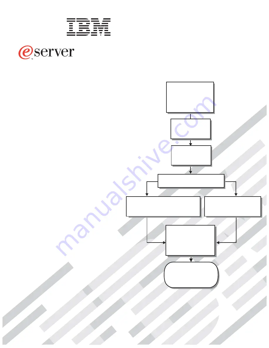
Install and start
the blade servers
Install addtional
applications, such as
IBM systems management
software and IBM
ServeRAID programs
System is ready to use.
Go to the Server Support
flowchart to register
and profile your server.
Install options:
• Drives
• Microprocessors
• SCSI storage expansion
• Memory
• I/O expansion
If the BladeCenter
is not installed in a
rack, install it now
BladeCenter HS20
Type 8678
Using RDM
See www.pc.ibm.com/ww/eserver/
xseries/systems_management/index.html
for instructions
Using the NOS
installation instructions
at www.ibm.com/pc/support
Install an operating system
(choose one method)
Summary of Contents for 8678
Page 3: ...BladeCenter HS20 Type 8678 Installation and User s Guide ERserver...
Page 52: ...38 BladeCenter HS20 Type 8678 Installation and User s Guide...
Page 60: ...46 BladeCenter HS20 Type 8678 Installation and User s Guide...
Page 62: ...48 BladeCenter HS20 Type 8678 Installation and User s Guide...
Page 84: ...70 BladeCenter HS20 Type 8678 Installation and User s Guide...
Page 89: ...Japanese Voluntary Control Council for Interference VCCI statement Appendix C Notices 75...
Page 90: ...76 BladeCenter HS20 Type 8678 Installation and User s Guide...
Page 94: ......
Page 95: ......
Page 96: ...IBM Part Number 48P9782 Printed in the United States of America 48P9782...


