


USER
MANUAL
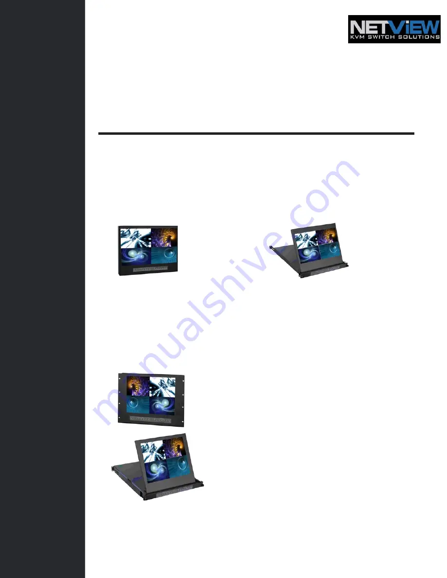
Widescreen LCD Quad Display
Wide 19”, 22” Screen Size
Widescreen LCD Quad Display
Models
NQW922
NQW819
4:3 LCD Quad Display
17", 19", 20" screen size
4:3 LCD QuaD Display
Models
NPQ817 / NPQ919 / NPQ1020
Options
: - DC Power
Widescreen LCD Drawer
Models
NQW119
4:3 LCD Display
Models
NPQ117 / NPQ119 / NPQ120


