

Connecting the T77 Directly to a Phone Jack
The T77 requires an operating telephone line and a
convenient area for operating the terminal. Insert the
cable that came with the terminal into a dedicated
analog telephone jack. (The use of a different cable
might result in improper operation.) Insert the other end
of the telephone line into the port labeled
LINE
on the
back panel of the terminal. Ensure that the telephone
line latches are firmly locked into the jacks on the
terminal and the wall receptacle.
Note: Hypercom terminals do not function
with digital phone lines.
Connecting the T77 With a Telephone
Connect one end of the telephone line to the back of the
telephone and connect the other end to the port labeled
P H O N E
on the back panel of the terminal. When the
line is connected, lift the handset and listen for a dial
tone. If you do not hear a dial tone, check the
connection again. The terminal displays
REPLACE HANDSET
when the phone is
in use and cannot perform dial transactions.
Powering up the T77
Connect the power (+24 Vdc) cable from the AC
Adapter to the three-pin port labeled
P O W E R
on the
back panel of the terminal. (The use of a different power
supply other than the one supplied with the unit may
result in improper operation.) Plug the Adapter into a
110-Volt grounded power receptacle. Be sure the
connector is firmly seated. When the power is connected
successfully, the terminal beeps twice and performs a self-
test and diagnostic routine. The software and downline
load status of the terminal is displayed during the self-
test, which takes approximately four seconds.
T77 Series
T E R M I N A L
I N S TA L L AT I O N
G U I D E
Phone
Power
Line
Introduction to the T77 Series Terminals
The T77 terminal series includes the T77F, T77S, T77G, T77Q, T77T and
T77GQ. With their high speed easily replaceable printer modules, the T77
terminal series are perfect for a wide range of applications. The T77 series supports
draft capture, debit, check and proprietary card processing. They also support new
payment vehicles such as chip card-based credit/debit cards and stored value cards.
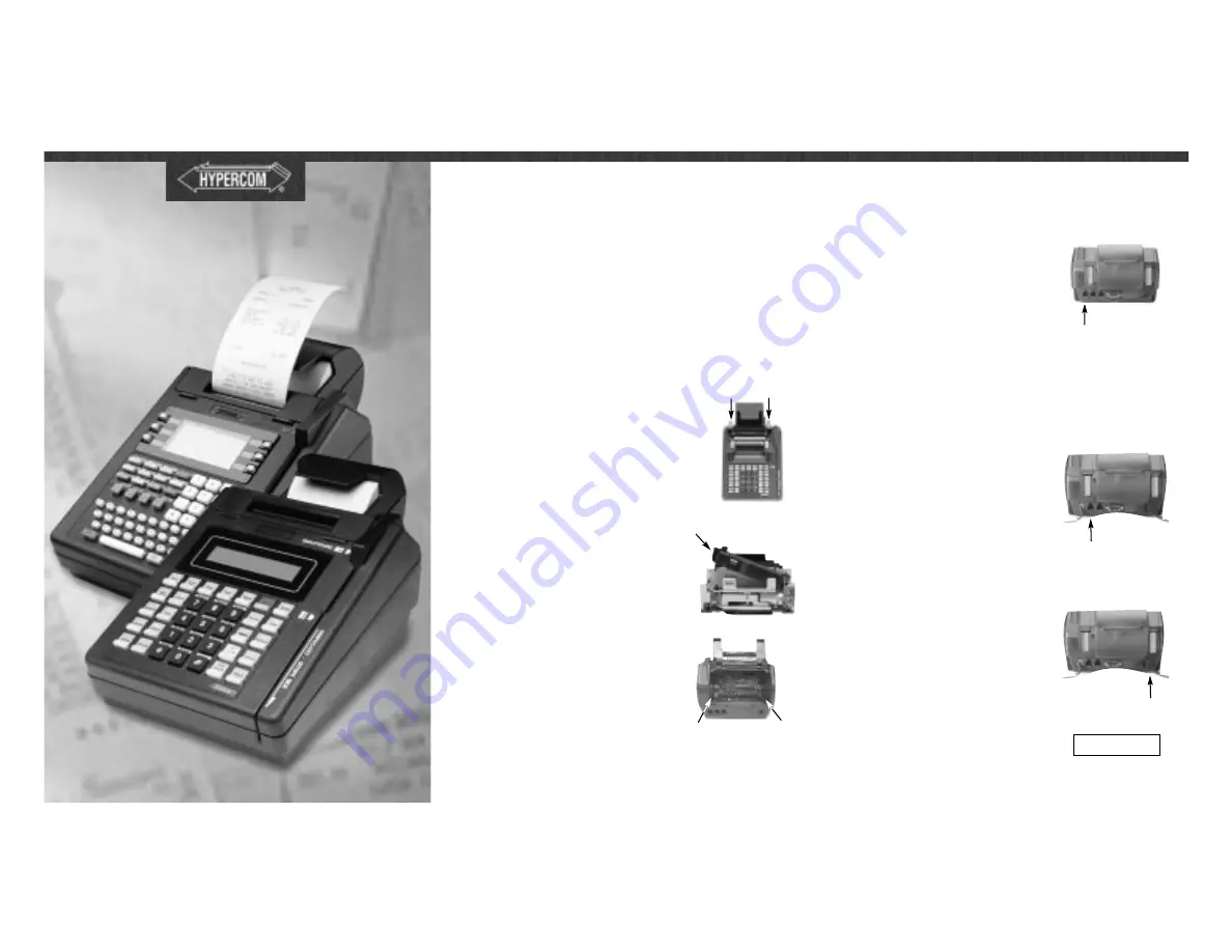
Setup and Maintenance
Inserting the Printer Ribbon and Printer Module
Release the two tabs on the tear bar cover, located at the
back of the terminal, by placing fingers on the tabs and
pulling the cover up.
Locate the gray levers on the back of the terminal
and push them down and away from you.
Carefully remove the modular printer by pulling
the printer mechanism away from the terminal.
Do not use the paper holder for leverage.
Tighten the new ribbon by rotating the ribbon
feed knob in the direction shown by the arrow
on the ribbon cassette. Place the new cassette
on the printer module allowing the ribbon to
slip into the printing gap.
Place the printer module into the terminal and
evenly slide the mechanism under the guides in
the bottom of the printer chassis until it stops.
Then, use the gray levers to guide the
mechanism into the terminal by pulling the
levers toward you.
Close the tear bar cover, then the paper cover,
and connect the power supply.
Lever
Lever
Guide
Guide
Ribbon
Cassette
[T7XXXXX] DLL-00
WAIT -SELF-TEST


