manualshive.com logo in svg
background image

1

Issue: 01
Part Number:  31500DXL
Date:  2020-04-13

UPS5000-E-(60 kVA

–125 kVA)  

Quick Guide (Integrated UPS 3.0)

1

Overview

Copyright © Huawei Technologies Co., Ltd. 2020. All rights reserved.
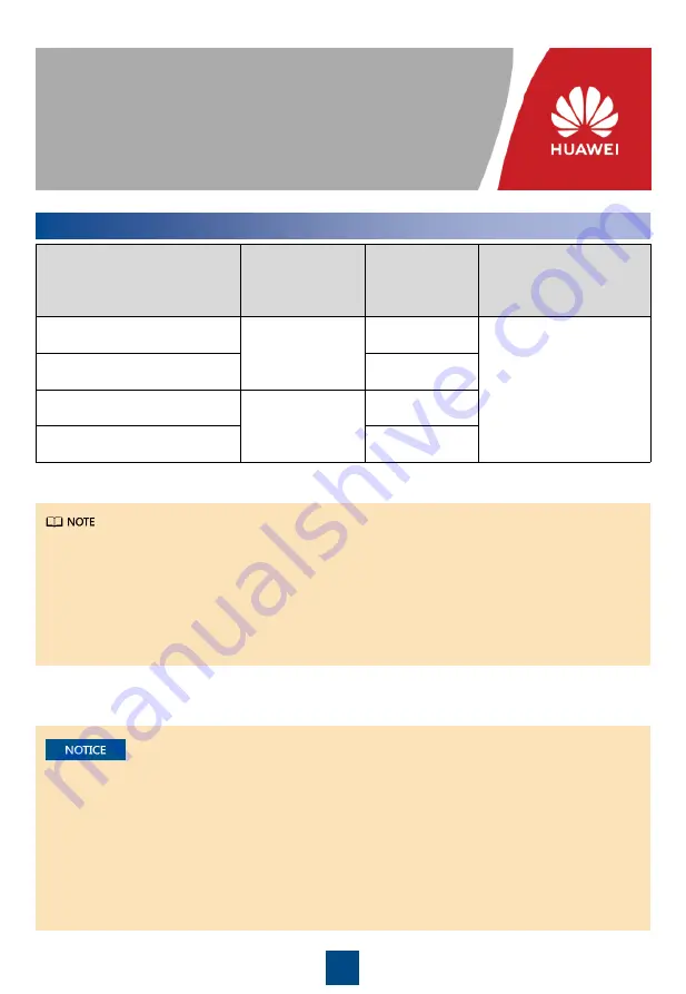
UPS Model

Capacity 

Configuration

Weight (Full 

Configuration)

Dimensions  (H x W x D)

UPS5000-E-50K-HABBS

30 kVA, 60 kVA

352 kg

2000 mm x 600 mm x 

1100 mm

UPS5000-E-50K-HASBS

390 kg

UPS5000-E-125K-HABBS-01

90kVA,  120kVA, 

125kVA

435 kg

UPS5000-E-125K-HASBS-01

453 kg

• The appearance  of the UPS5000-E-60K-HABBS  (02312TVW, 02312TWB) is similar  to that  of 

the UPS5000-E-125K-HABBS-01  (02312TVY,  02312TWC).

• The appearance  of the UPS5000-E-60K-HASBS  (02312TVX)  is similar to that of the UPS5000-

E-125K-HASBS-01  (02312TWA).

• If Requisite modules is set to 5, the maximum output capability of each module is 25 kVA/25 kW.

1. Before  installation,  read  the user manual  carefully  to get  familiar  with product  information  and 

safety  precautions.

2. Use insulated  tools  during installation.

3. Only engineers  certified  by Huawei  or its agents  are  allowed  to install,  commission,  and 

maintain  the UPS. Otherwise,  personal  injury  or equipment  damage  may  occur, and  the UPS 

faults caused  are  beyond  the warranty  scope  of Huawei.

Содержание UPS5000-E-125K-HABBS-01

Страница 1: ... 02312TVW 02312TWB is similar to that of the UPS5000 E 125K HABBS 01 02312TVY 02312TWC The appearance of the UPS5000 E 60K HASBS 02312TVX is similar to that of the UPS5000 E 125K HASBS 01 02312TWA If Requisite modules is set to 5 the maximum output capability of each module is 25 kVA 25 kW 1 Before installation read the user manual carefully to get familiar with product information and safety prec...

Страница 2: ...odule 12 Monitor display unit MDU 13 Power distribution monitoring board 14 UPS output circuit breaker UPS5000 E 60K HABBS 1 Power input status indicator 2 Input circuit breaker 3 Lighting circuit breaker 4 Power distribution circuit breaker for the mart cooling product 5 IT load circuit breaker 6 UPS input circuit breaker 7 UPS maintenance bypass circuit breaker 8 Control module 9 Bypass module 1...

Страница 3: ...1 Determine the mounting holes based on the marking off template drill holes and install expansion sleeves unit mm 3 Secure the UPS 2 Adjust the anchor bolts and ensure that the anchor bolts touch the floor Then level the UPS ...

Страница 4: ...emove the rear door of the cabinet hinges connecting plates and ground cable 4 Adjust the tail frame anchor bolts until the tail frame is as high as the cabinet Then secure the tail frame to the UPS 5 Install the hinges connecting plates and rear door on the tail frame 6 Connect the ground cable to the rear door of the cabinet 4 Optional Combining Cabinets The figures are for reference only The ac...

Страница 5: ...ne other cabinets 6 Secure the bolts using a socket wrench Prepare cables away from the cabinets to prevent scraps from falling inside Cable scraps may ignite and cause personal injury or device damage After cables have been installed clean the cabinet in a timely manner Ensure that there is no foreign matter inside and around the cabinet You need to prepare terminals onsite The stripped length of...

Страница 6: ...route is for reference only Connect cables based on site requirements 1 Remove the insulation protective panel from the rear of the cabinet and remove covers from the top as required 2 Connect a ground cable to the UPS cabinet ATS input 3 Connect the AC input power cable MCCB input ...

Страница 7: ...p Cables ATS input cabinet Port Description Bolt Specifications Bolt Length Torque AC input M12 45 mm 46 N m Battery input M10 30 mm 26 N m PE M12 45 mm 46 N m Safe grounding M6 16 mm 4 5 N m Route a neutral wire from the middle of the positive and negative battery strings Take a battery string consisting of 40 batteries as an example A neutral wire is routed from the middle of positive and negati...

Страница 8: ...s in other cabinets see the procedure in this section Connect the inside cables first and then the outside cables 1 Remove the cover plate from the cable hole at the bottom of the tail frame 2 Remove the insulation panels at the rear of the cabinet 3 Connect a ground cable to the safety ground of the UPS cabinet 4 Connect AC input power cables Scenario 2 Routing Cables from the Bottom ...

Страница 9: ... 2 The following figure uses cable routing from the top as an example Lighting wiring terminal Smart cooling product wiring terminal IT wiring terminal Connect a communications cable between the FE port on the UPS monitoring interface card and any PoE port on the ETH gateway Connecting Communications Cables to Northbound Devices ...

Страница 10: ... top and bottom of the cabinet copper bars switches and the rear of modules Optional Connecting SmartLi Communications Cables Connect one end of the cable to the COM1 port on the UPS monitoring interface card and connect the other end to the COM port on the SmartLi monitoring interface unit ...

Страница 11: ...ot attempt to install or maintain the device 7 Before performing maintenance tasks ensure that the power supply to the switch is disconnected 3 After verifying the installation reinstall all the covers After the installation is complete reinstall the dustproof cover to prevent dust inside if the UPS is not to be powered on immediately 1 Before power on operate the handle to switch on and off the A...

Страница 12: ...k whether the controller has alarms If an alarm exists rectify the fault first View the alarm ID on the controller LCD If LN 1 and LN 2 power indicators are hollow there is an alarm Locate the fault based on the alarm ID and the alarm ID reference list on the 8D controller and rectify the fault 1 LN 1 power status 2 LN 2 power status 3 LN 1 power alarm ID 4 LN 2 power alarm ID 3 Press the locking ...

Страница 13: ...uawei engineers 2 When the controller is in button mode do not simultaneously press and hold down the I II and O buttons on the controller panel Ensure that the interval between two commands is 5s at least If another command is issued before the previous one is executed the protection fuse F1 under the electric operation mechanism may be blown 6 Set the 8D controller to Auto mode Check whether the...

Страница 14: ... are OFF Powering On the UPS 8 1 Switch on the UPS input circuit breaker QF1 The UPS works in normal mode and starts initialization The LCD displays the Huawei logo and an initialization progress bar Close the upstream input switch Is MCCB input used Yes Switch on the MCCB No ATS input is used Commission the ATS by following the instructions in chapter 7 ATS Commissioning Before System Power On Me...

Страница 15: ...in Enter Bar code and Verification code obtained from the LCD on the Offline Activation screen Tap Generate PWD to generate a startup password Set Site and Device Type as required and tap Offline Activation Enter the generated password in the password textbox on the LCD to start the UPS Use the app to start the UPS online Yes No start the UPS offline On the app home screen tap StartUp to access th...

Страница 16: ...16 2 Set the language time date network parameters and system parameters on the Settings Wizard screen ...

Страница 17: ...se Common Functions and tap Inv ON 2 In the displayed login window enter the user name and password and tap 3 In the displayed dialog box tap Yes to start the inverter Starting inverter 8 3 To ensure system security change the LCD passwords after the first login 1 Close the battery string circuit breaker If there are multiple battery strings close the circuit breaker for each battery string and th...

Страница 18: ...own 1 On the main menu of the LCD choose Common Functions and tap Inv OFF 2 In the displayed dialog box tap Yes to shut down the inverter Shutting Down the Inverter to Transfer the UPS to Bypass Mode 9 1 Powering Off a Single UPS 9 2 Turn off the downstream output switch and battery string switch Turn off the UPS input switch and output switch Turn off the MCCB skip this step in the case of ATS in...

Страница 19: ...ed in battery mode for a long time The charger is faulty 1 Check whether the battery voltage is normal 2 Check whether the output is overloaded 3 Check whether any battery is damaged If yes replace the battery 4 Check whether a charger alarm is triggered If a charger is faulty replace the related faulty power module Mains voltage abnormal The mains voltage exceeds the upper threshold or is below t...

Страница 20: ...China www huawei com Scan here for more documents You can also log in to Huawei technical support website https support huawei com enterprise https support huawei com Support Support E WeChat Scan here for technical support enterprise Scan here for technical support carrier Huawei App Store Huawei App Store ...

Отзывы: