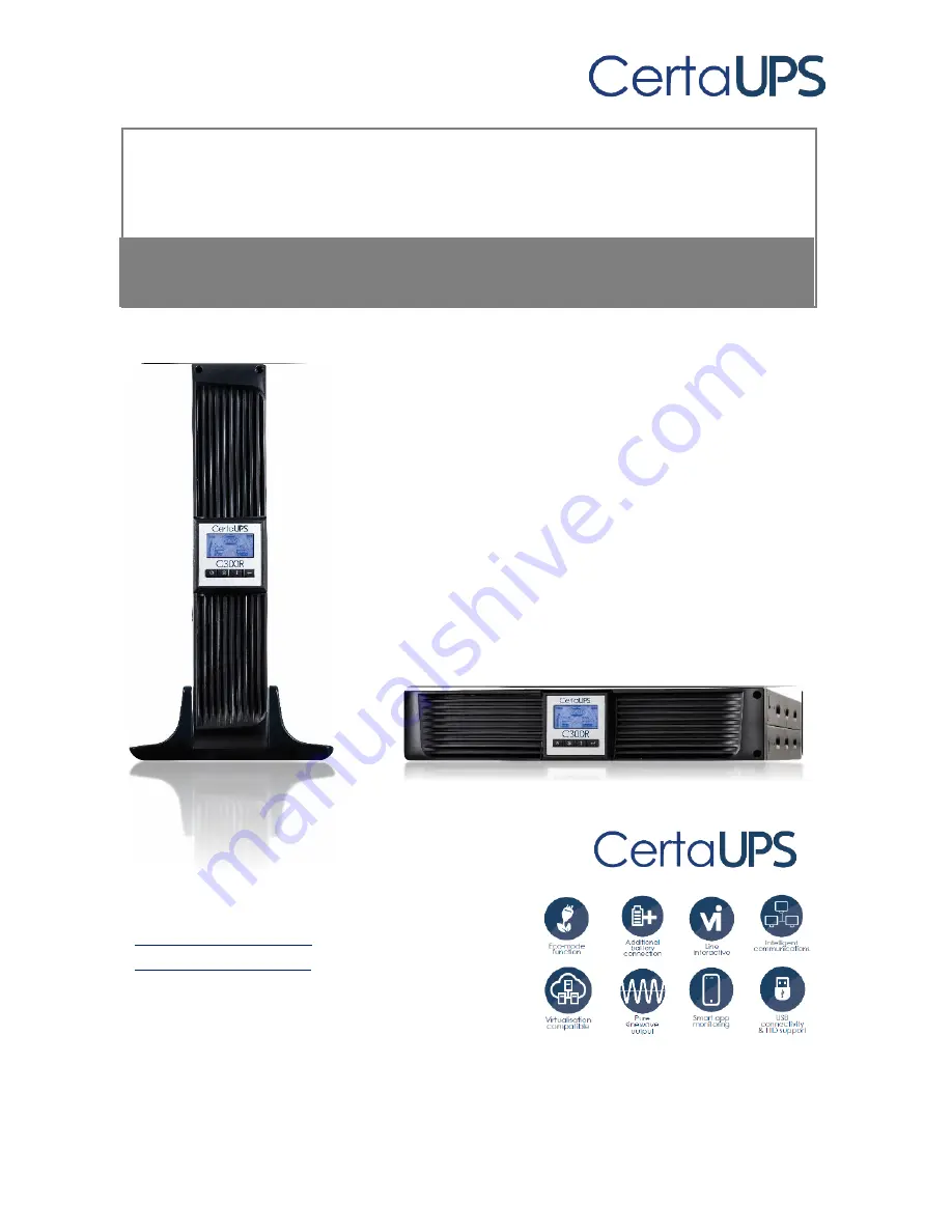
manualshive.com logo in svg
background image


C300R 1-3 kVA 

Rack/Tower 

1000-3000VA


Installation/Manual 

Service and support 

WWW.CERTAUPS.COM 
[email protected] 

T: +44 (0)1246 431 431 

Содержание C300R-020-B

Страница 1: ...1 C300R 1 3 kVA Rack Tower 1000 3000VA Installation Manual Service and support WWW CERTAUPS COM INFO CERTAUPS COM T 44 0 1246 431 431 ...

Страница 2: ...00 3000VA series that should be followed during the installation and maintenance of the UPS and batteries Please read all safety and operating instructions before operating the UPS Adhere to all warnings on the unit and those contained within this manual Please also follow all operating and user instructions provided ...

Страница 3: ...en Function 33 5 Communication Port 34 5 1 RS 232 and USB Communication Ports 34 5 2 Emergency Power Off EPO 35 5 3 Network Management Card Optional 36 6 UPS Maintenance 36 6 1 UPS and Battery Care 36 6 2 Storing the UPS and Batteries 36 6 3 Time to Replace the Batteries 38 6 4 Replacing the UPS Internal Batteries 39 6 5 Testing New Batteries 43 6 6 Recycling the Used Battery 44 7 Specification 45...

Страница 4: ...ont panel of the UPS includes an LCD display with four control buttons that allow the user to monitor configure and control the unit On the LCD a graphical bar two status indicators and four alarm indicators are included See image A control button from the front panel allows the user to turn off the AC fail alarm and initiate the UPS self test sequence The UPS case is made of metal This UPS is pow...

Страница 5: ...le EBM Built in boost and buck Automatic Voltage Regulator AVR Built in Dry contact RS 232 USB communication ports Microprocessor control guarantees high reliability High frequency design SNMP allows for web based remote or monitoring management Optional Overload short circuit and overheat protection Rack Tower 2 in 1 Design 19 rackmount available for all models ...

Страница 6: ...onment free of conductive contaminants Ambient 0 40 C To reduce the risk of fire please connect to a circuit breaker rated at 20A To comply with international standards and wiring regulations the total leakage current of the UPS and the connected loads must not exceed 3 5mA The electrical supply that feeds the UPS shall be installed near the UPS and shall be easily accessible Disconnection of an e...

Страница 7: ...knowledge of batteries and the required precautions Keep untrained personnel away from the batteries The safe disposal of batteries is required Refer to your local environmental regulations e g WEEE Regulations for disposal requirements Never dispose of batteries in a fire Batteries may explode when exposed to flames The following block diagram shows the basic internal circuit configuration of the...

Страница 8: ...se themselves with their definitions Table1 Description of Commonly Used Symbols 3 Installation 3 1 Inspection of unit Visually inspect the UPS for damage upon receipt If the internal packaging or UPS has been damaged during shipment keep the box and packaging materials in their original form notify the carrier and contact the supplier immediately ...

Страница 9: ... for tower or rack orientation Please follow the instructions on the next few pages that relate to the configuration that s best for your system Tower The C300R can be placed either horizontally or vertically An optional stand is included with this UPS in order to allow for tower configuration The stand can be used in order to position the UPS in an upright position In order to achieve this the UP...

Страница 10: ...10 1 Carefully place the UPS within the stands 2 Slide the UPS stands to each end of the tower ...

Страница 11: ...11 ...

Страница 12: ...12 2 Pull out the LCD panel and rotate it in a clockwise direction to 90 degrees and then push it back into the front panel The LCD is on a short wire please take care when executing this step ...

Страница 13: ...f rack space for each additional EBM installed an additional 2U rack space is required Use the following procedure to install the UPS within a rack cabinet 1 Align the mounting ears with the screw holes on the side of the UPS and tighten the screws 2 Assemble the rack rails with the rackmounting ...

Страница 14: ...14 3 Slide the UPS into the rack rails and lock it into the rack enclosure 4 Tighten the screws The UPS is now ready for cabling unless you are installing EBMs ...

Страница 15: ...15 ...

Страница 16: ...the EBM in Tower form 1 Position the UPS and EBM within the extended UPS stands then slide the stands to either end of the tower 2 Tighten the screws on the UPS cover for stabilisation 3 Connect an Earth line from the UPS port A to the EBM port B ...

Страница 17: ...d the small blanking plate on the side of the front panel in order to remove it This then enables you to connect battery terminal A from the UPS to the EBM terminal B shown below After doing this reassemble the front panel 5 After setting up the UPS the load can then be connected Please make sure the load equipment is turned off before connecting all loads into the output C13 C19 ports ...

Страница 18: ...18 Connecting the EBM in a rack form 1 Using the same method as assembling the UPS in rack form assemble the EBM into the rackmounting above or below the UPS ...

Страница 19: ... the front of the UPS and carefully take out the LCD screen and remove the screw Finally push inward the small blanking plate on the side of the front panel in order to remove it This then enables you to connect the battery terminal A from the UPS to the EBM terminal B shown below After doing this reassemble the front panel ...

Страница 20: ...20 5 After installing the UPS into the rack the load can then be connected to the UPS Please make sure the load equipment is turned off before connecting all loads into the output C13 C19 ports ...

Страница 21: ...Ms in order to provide additional backup time In order to do this please follow the instructions provided on the next few pages of this manual Connecting multiple EBMs in Tower form 1 Connect an Earth line between the UPS and the first EBM and then connect a second Earth line between the first EBM and the second EBM ...

Страница 22: ...al screw Finally push inward the small gate on the side of the front panel in order to remove it This then enables you to connect the battery terminal A from the UPS to the EBM terminal B shown below Then connect the battery terminal D from the first EBM to the battery terminal E of the second EBM The user then needs to reassemble the front panel ...

Страница 23: ...screws from the front of the UPS and carefully take out the LCD screen and remove the screw Finally push inward the small gate C on the side of the front panel in order to remove it This then enables you to connect the battery terminal A from the UPS to the EBM terminal B shown below Then connect the battery terminal D from the first EBM to the battery terminal E of the second EBM After doing this...

Страница 24: ... power button for longer than 3 seconds to turn on the UPS Once this is done the UPS status display will change to NORM 5 Check the UPS display for active alarms or notices Resolve any active alarms before continuing See Troubleshooting on page 41 for an overview of possible problems and how to resolve them 6 If optional EBMs are installed see Configuring UPS for EBM numbers to set the number of i...

Страница 25: ...he standard backlight is used to light up the display with black text and a blue background When the UPS has a critical alarm the backlight changes the background to red See the diagram below for an illustration of the LCD panel Control buttons functions There are four buttons on the LCD control panel ...

Страница 26: ...n 3 seconds To remove the UPS from fault mode Disconnect the mains input to the UPS and then press and hold the power button for longer than 2 seconds to shutdown the UPS UPS Test Alarm Silence To perform basic function test Press and hold the button for 3 seconds To perform battery life test Press and hold the button for 10 seconds To disable alarm buzzer Press the button for one second Select Pr...

Страница 27: ...The list of events shown below prevents the disabling of the alarm buzzer Low Battery Fan Failed Fan Fault Time Out and Overheat Note The user can disable the alarm buzzer when it s sounding but an alarm will still sound when a new alarm event is encountered Table2 Description of LCD display functions Description Function Input frequency and voltage Indicates the value of input frequency and volta...

Страница 28: ...on Settings light This light will turn on when the UPS is within settings mode Battery capacity level indicator This light indicates the amount of battery capacity remaining Each battery capacity level bar indicates 20 of the total battery capacity Load capacity level indicator Indicates the percentage of the UPS load capacity which is being used by the protected equipment Each LCD level bar indic...

Страница 29: ...batteries AVR The UPS is operating in AVR mode bATT The UPS is providing power to equipment from the UPS batteries This will occur if there s a problem with the mains supply UPS will follow shutdown procedures established using the WinPower Software TEST The UPS is currently set to perform tests on the batteries OPVH Displayed during battery operation if the input voltage is too high above maximum...

Страница 30: ...uto self test function 000 Disable 001 Enable AR Automatic restart 000 Disable 001 Enable GF Green function 000 Disable 001 Enable bZ Buzzer control 000 Disable 001 Enable LS1 Load segment 1 000 Turn off 001 Turn on LS2 Load segment 2 000 Turn off 001 Turn on 4 2 Operating Mode Normal range mode The UPS accepts an AC input voltage within the range of 20 Generator mode The low frequency transfer po...

Страница 31: ...y string shows STbY to indicate that power is not available to your equipment The battery recharges when necessary 4 3 Configuring load segment The Load Segment is a set of C13 C19 ports that can be controlled through the LCD display Each UPS has two configurable load segments See Rear Panels on pages 39 40 for images which show all connections on the back of the UPS including the load segment AC ...

Страница 32: ...he Enter button for one second and the UPS will then return to settings mode 6 Exit Settings mode Press and hold the Enter button for 3 seconds or the power button for 0 5 second to exit settings mode 4 4 Configuring UPS for EBM numbers To ensure the LCD displays the correct battery capacity configure the UPS for the correct number of EBMs 1 Enter settings mode Press and hold the Enter button for ...

Страница 33: ...f load being supported If an insignificant level of load is detected the UPS will shutdown automatically but only if it s currently operating from the batteries The green function is disabled by default but the user can configure the Green Function through the display 1 Enter settings mode Press the Enter button for longer than 3 seconds to enter settings mode 2 Select settings items Press the Sel...

Страница 34: ...nication cable is installed power management software Winpower can exchange data between the computer and the UPS The software polls the UPS for detailed information on the status of the power environment The software can be configured so that in the event of a power cut it initiates the saving of all data and the safe shutdown of the protected equipment The pin configuration for the RS 232 commun...

Страница 35: ...e EPO must not be connected to any mains supply source Cabling for the EPO circuit should be isolated from sources of interference i e mains supply The EPO Switch must have a minimum rating of 24VDC and 20mA and be a dedicated latching type switch not tied into any other circuit The EPO signal must remain active for at least 20ms for proper operation EPO Connections Wire Function Terminal Wire Siz...

Страница 36: ...ty Please contact your supplier if you require an SNMP card 6 UPS Maintenance 6 1 UPS and battery care For the best preventative maintenance keep the area around the UPS clean and dust free If the atmosphere is very dusty clean the outside of the system with a vacuum cleaner For long battery life keep the UPS at an ambient temperature of 20 25 C 77 F 6 2 Storing the UPS and batteries When the UPS ...

Страница 37: ...37 to 90 capacity in approximately 4 hours However it is recommended that the batteries charge for 48 hours after long term storage ...

Страница 38: ...rstanding of the required precautions Keep unauthorised personnel away from batteries Batteries can present a risk of electrical shock or burn from high short circuit currents The following precautions should be observed when working on batteries 1 Remove watches rings or other metal objects 2 Use tools with insulated handles 3 Do not lay tools or metal parts on top of batteries 4 Wear rubber glov...

Страница 39: ...mage the battery Released toxic electrolyte is harmful to skin and eyes Note If you are not qualified to replace the batteries do not attempt to open the battery cabinet Please call your supplier 6 4 Replacing the UPS internal batteries Follow the steps and charts shown below in order to replace the batteries 1 Take off the LCD panel and remove the screws 2 Slide and pull the front panel as indica...

Страница 40: ...40 ...

Страница 41: ...41 3 Disconnect the cable from the UPS and battery pack 4 Remove the right inner battery bracket 5 Pull the battery pack out onto a flat surface ...

Страница 42: ...42 ...

Страница 43: ... Batteries For a battery test please check The batteries must be fully charged The UPS must be in Normal mode with no active alarms Don t connect disconnect equipment to from the UPS To test batteries 1 Connect the UPS to mains power for at least 48 hours to charge the batteries 2 Press and hold the button for 10 seconds to start the battery test The status display string will show TEST ...

Страница 44: ...ttery can present a risk of electrical shock and high short circuit current To properly recycle the used battery please do not discard the UPS battery pack and batteries into the general waste Please follow your local environmental regulations e g WEEE Regs you may contact your local recycling waste management centre for further information to properly dispose of the used UPS battery pack and batt...

Страница 45: ...ode 5 Frequency 50Hz or 60Hz Waveform Pure Sinewave Overload rating Line Mode 110 0 8 shutdown after 3 minutes 150 0 10 shutdown after about 200ms Battery Mode 110 6 shutdown after 30 seconds 120 6 Shutdown after about 100ms Internal battery Battery Type 3 12V 7AH 3 12V 9AH Backup Time at full load mins 4 5 3 Recharge Time 3 hours to 90 after discharged 4 hours to 90 after discharged External batt...

Страница 46: ...form Pure Sinewave Overload rating Line Mode 110 0 8 shutdown after 3 minutes 150 0 10 shutdown after about 200ms Battery Mode 110 6 shutdown after 30 seconds 120 6 Shutdown after about 100ms Internal battery Battery Type 6 12V 7AH 6 12V 9AH Backup Time at full load mins 4 5 3 Recharge Time 3 hours to 90 after discharged 4 hours to 90 after discharged External battery module EBM Battery Type 12V 7...

Страница 47: ...ill show a red screen and OVLD Low Battery LCD will show a red screen and bTLW Audible alarm Backup Mode Sounding every 4seconds Low Battery Sounding every second UPS Fault Continuously Sounding Overload Sounding every second Battery Replacement Sounding every second Table 9 Operating Environment Temperature 20 25 C Humidity 20 80 relative humidity non condensing Altitude 1500m Storage Temperature...

Страница 48: ...38x86 5x436 438x86 5x608 EBM Case Dimension mm WxHxD 438x86 5x436 438x86 5x608 Net weight kg 20 5 33 3 7 2 Rear Panels No Function C300R 010 B C300R 015 B 1 AC Output 2 Modem Network Surge Protection 3 SNMP Port 4 AC Input 5 RS 232 Dry Contact Communication Port 6 USB Port 7 EPO 8 Earth Line Connection C300R 010 B C300R 015 B Standard model rear panel ...

Страница 49: ...30 B 1 AC Output 2 Modem Network Surge Protection 3 SNMP Port 4 Fan 5 AC Input 6 RS 232 Dry Contact Communication Port 7 USB Port 8 EPO 9 Earth Line connection C300R 020 B Standard model rear panel C300R 030 B Standard model rear panel ...

Страница 50: ... Indication Cause Solution Sounding every 4 seconds The UPS is on battery mode Check the input voltage Sounding every second and bATL on screen The battery voltage is low Save your work and turn off your equipment Sounding every second and OVLD on screen Output overload Check load level indicator and remove some load Continuously sounding and red display The UPS has failed Please contact your supp...

Страница 51: ...put jumpers No power on output receptacle Check if the LS1 and LS2 are set up from 001 to 000 Backup time is short Battery is empty Re charge the battery for at least 24 hours Battery aging Replace the battery Continuously sounding and display background is red The UPS has failed Please contact your supplier Buttons not working correctly The setting mode is not configured correctly Please see righ...

Страница 52: ...he same LAN regardless of distance from the UPSs Installation procedure 1 Go to the website http www certaups com software 2 Choose the operating system you use and follow the instructions described on the website to download the software 3 When downloading the required files from the internet enter the product key 511C1 01220 0100 478DF2A to initiate installation of the software When the computer...

Отзывы: