Hougen 10909(S), Operator'S Manual
The Hougen 10909(S) Operator's Manual is available for free download on our website. This essential manual provides detailed instructions for operating and maintaining your Hougen 10909(S). Ensure proper usage and care of your equipment by downloading the manual from manualshive.com today.
Share
Download


Reviews:
No comments
Related manuals for 10909(S)
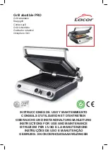
PRO
Brand: Lacor Pages: 88

Handy Master ABS9
Brand: Fein Pages: 4

MAYER BARBECUE MKG-316 BASIC
Brand: BRENNA Pages: 4

T30943
Brand: Grizzly Pages: 40

1921B1
Brand: Beta Pages: 76

GALACTIC GRILL
Brand: G3 Ferrari Pages: 32

PSB13-C5
Brand: P.I.T. Pages: 21

463870109
Brand: Char-Broil Pages: 32

KS12107
Brand: Montana Pages: 21

eBBQ PG 8113 SENOA BOOST
Brand: SEVERIN Pages: 52

VAC-FORCE 1557
Brand: Sioux Tools Pages: 52

86019
Brand: FLORABEST Pages: 52

CDL-7100
Brand: Ozito Pages: 8

WS2539
Brand: Wesco Pages: 36

Avalon series
Brand: Landmann Pages: 147

CBT-12081W
Brand: Backyard Pages: 16

Summit Gold D 42080
Brand: Weber Pages: 50
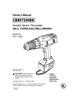
973.111290
Brand: Craftsman Pages: 16


