background image

INSTALLATION INSTRUCTIONS

69-2432-01

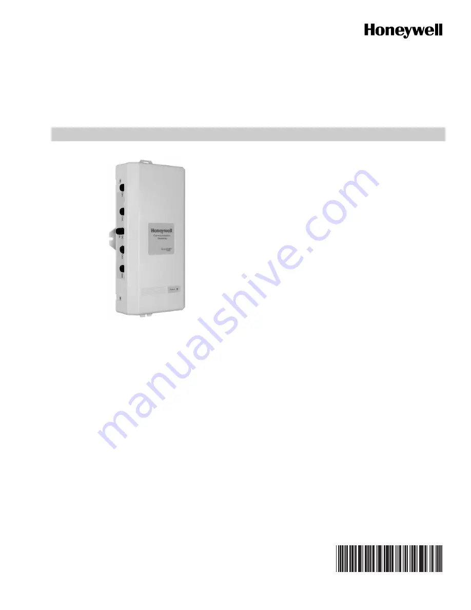
W8735G Communication Gateway

APPLICATION

For use with Remote Access applications monitoring 

EnviraCOM™ enabled controls and sensors. Communicates 

with up to four EnviraCOM™ buses for multiple appliance 

installations.

COMPONENTS AND 
ACCESSORIES

• R7184 Oil Primary

• R7284 Oil Primary

• L7224 Aquastat®

• L7248 Aquastat®

• TH9421C VisionPRO® IAQ

• W8735S1016 Indoor Temperature Module for temperature 

indication and alerting.

FEATURES

• Monitors the bus for critical events and updates the 

server.

• Monitors system power and generates power failure 

alarms.

• Battery backup.
• Monitor up to four separate appliances.
• Updates via phone line or network.
• Auxiliary I/O.
• Remote firmware updates.

When Installing This Product…

1.

Read these instructions carefully. Failure to follow the 

manual could damage the product.

2.

Installer must be a trained, experienced service techni-

cian.

3.

Complete all wiring connections to the gateway before 

powering up the 24Vac system transformer and plug-

ging in the gateway power supply into an outlet.

4.

All wiring must comply with applicable local electrical 

codes, ordinances and regulations.

INSTALLATION

Mount the W8735G in the equipment room near the indoor 

HVAC equipment. Position the W8735G vertically so that the 

power and telephone plugs are situated towards the bottom or 

horizontally so that all wiring terminations face the floor, 

depending on the space available. See Fig. 1.

IMPORTANT

Turn OFF all power to heating and cooling equip-

ment.

1.

Position the W8735G on a wall near the indoor HVAC 

equipment. Level the module for appearances only; the 

module functions properly even when not level.

2.

Use a pencil to mark the mounting holes to be used. 

The W8735G has two external mounting holes and two 

external flanges. See Fig. 2.

3.

Use a minimum of one hole and one flange to mount the 

W8735G.

Summary of Contents for W8735G

Page 1: ...duct 2 Installer must be a trained experienced service techni cian 3 Complete all wiring connections to the gateway before powering up the 24Vac system transformer and plug ging in the gateway power supply into an outlet 4 All wiring must comply with applicable local electrical codes ordinances and regulations INSTALLATION Mount the W8735G in the equipment room near the indoor HVAC equipment Posit...

Page 2: ...allasts and large distribution pan els Failure to follow these wiring practices may intro duce electrical interference noise which can cause erratic system operation All unused wire is to be grounded at controller end only The bus wire to ter minal 1 D must not exceed 1 000 feet 305 M General Wiring Directions Refer to Fig 3 and Table 1 for the location and function of each terminal IMPORTANT Wire...

Page 3: ...ary Output DO Connect to N O contact alarm input Auxiliary Output DO Connect to N O contact alarm input Auxiliary Input DI Connect to N C sensor contact 18 30 Vac Vdc Auxiliary Input DI Connect to N C sensor contact 18 30 Vac Vdc Channel 3 Model 1018 only 1 D channel 3 To EnviraCOM channel 3 network DATA 2 R channel 3 To EnviraCOM channel 3 network 24 Vac Hot 3 B channel 3 To EnviraCOM channel 3 n...

Page 4: ...MMUNICATION GATEWAY TO OPTIONAL ENVIRACOM CONTROLS AND SENSORS M29961 1 D 2 R 3 B THERMOSTAT OPTIONAL REVIEW COMPONENTS AND ACCESSORIES SECTION FOR COMPATIBLE DEVICES 1 VISIONPRO IAQ 2 2 1 TELEPHONE POWER NETWORK 1 2 3 R7184U OIL PRIMARY CONTROL Status Event Priority Description LED Color Flashes Battery good LOWEST Normal Operation Green Solid Battery low Replace the battery Green Off Battery dea...

Page 5: ...se NOTE The Auxiliary Output is made on all alert conditions and is deactivated when the alert is cleared from the communication bus IMPORTANT Make sure the current draw through the Auxiliary Output terminals does not exceed specifications Use relays or contactors to integrate to line voltage devices Fig 6 AUX IN and AUX OUT Terminals located on the main circuit board Auxiliary Input and Output Ap...

Page 6: ...HANNEL 2 OUTPUT INPUT AUXILIARY POWER FROM THE AUXILIARY INPUT SUPPLIED BY TRANSFORMER 1 T87 OR SIMILAR 1 M23753 1 D 2 R 3 B 1 D 2 R 3 B COMBINATION OF DEVICES CONNECTED IN SERIES TO ANNUNCIATE ON ANY EVENT ON THE AUX IN LOOP 1 CHANNEL 1 CHANNEL 2 OUTPUT INPUT AUXILIARY 1 M23754 1 D 2 R 3 B 1 D 2 R 3 B N C N C COMBINATION OF DEVICES CONNECTED IN PARALLEL TO ANNUNCIATE ON AN AND EVENT ON THE AUX IN...

Page 7: ...ate the server every 30 minutes Applications requiring closer monitoring and faster updates should be connected to a network connection Upon power up the gateway will conduct a self test which includes a broadband or dial up attempt using a pre programmed 800 number Dial up connections are only used in cases where Broadband connections are unavailable For best performance connect to both Network a...

Page 8: ...his routine is repeated between midnight and 4 00 AM local time at which point dial out attempts cease The routine is repeated during the next reporting time of midnight 4 00 AM IMPORTANT For best gateway performance connect to both the network and phone Gateway Updates Periodically the gateway may require a firmware upgrade to enable new features supported by the web application This will occur a...

Reviews: