iPCAM-PT Pan and Tilt Wireless Internet Video Camera – Quick Installation Guide
For Online Support visit: http://www.security.honeywell.com/hsc/resources/MyWebTech/
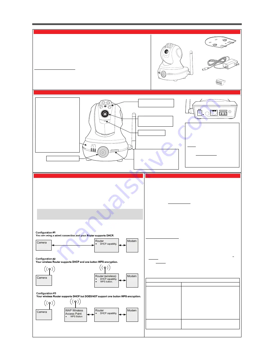
General Information
Mounting Plate
Power Transformer
This guide provides information on installing and setting up Honeywell's iPCAM-PT Camera. This camera is
ideal for monitoring your home, business or public facilities. Some major features of this camera are:
Wired or Wireless communications to a router or access point. Wireless communications utilizes the
802.11g protocol with WPS security. WPS (Wi-Fi Protected Setup) is a standard for easy setup of a secure
wireless network.
Pan and Tilt Color video can be controlled and monitored through your Total Connect remote services
account. Up to 6 cameras can be used.
Auxiliary LED lighting that improves the quality of video up to 15 feet in low-level light situations.
IMPORTANT: This camera is for indoor use only. To avoid damage to the drive mechanism, do not manually
pan or tilt the camera. DO NOT mount this camera within one [1] foot of any wireless device.
To utilize this camera, you must have:
Security system with a GSM, i-GSM or internet communications device.
Total Connect account. (If an account does not exist, the dealer should use the AlarmNet Direct website to
setup a Total Connect account for the customer.)
Internet access with a router capable of DHCP hosting. For wireless, the router must also support one
button WPS data encryption. If this is not available, order the Honeywell WAP Wireless Access Point for
connection to your router.
PACKAGE CONTENTS
Camera
GPIO Connector
(Future use.)
Component Identification
POWER
ACTIVE
NETWORK
GND
GND
DO
DI
SPKR
OUT
LAN
POWER RESET WPS
1. Mount the Camera
2. Power and Configure Wireless Security
On horizontal mounting surfaces, such as a shelf, the mounting plate is typically not necessary. However
if there is vibration, or the mounting surface is very small you may choose to use the mounting plate.
This will ensure the camera does not move from vibration or if the wires are tugged.
1.
If mounting the camera to a vertical or overhead surface, use the Mounting Plate. Use all three holes
in the Mounting Plate along with screws that are suitable for the mounting surface (do not use flat
head screws).
2.
Slide the camera onto the Mounting Plate until fully seated as indicated by a clicking sound.
3.
Orient the antenna vertically.
4.
Connect the Power Transformer wire to the Power Connector on the camera back.
At this time
DO NOT plug the power transformer in.
IMPORTANT: In order for the camera to be placed in the wired mode, the Ethernet cable must be
connected first, then power applied. Likewise in order for the camera to be placed in the wireless
mode, ensure the Ethernet cable is NOT connected, then apply power. Follow the directions on the
right carefully for applying power.
NOTE: The Power Transformer must be powered by a non-switchable power outlet.
5.
Refer to the diagram below, and determine which configuration applies.
If you have Configuration #1 –
Connect each camera to the router using an Ethernet
cable. Then plug the Power Transformer into an outlet. The camera installation is DONE.
If you have Configuration #2 –
Complete all the steps below.
If you have Configuration #3 –
You must attach the optional Honeywell WAP Wireless
Access Point to the router, then complete all the steps below.
NOTES:
When setting up a wireless configuration in very large buildings or buildings with dense
walls, wireless communications may be marginal. It is best to first configure the system
in the same room. Then upon successful configuration, place each camera in the
desired location. Check to see that all cameras exhibit good communications as
indicated by a STEADY GREEN Power LED and a Network LED that occasionally
BLINKS GREEN.
If using more than one wireless camera, each must be configured for wireless security.
If using a router instead of Honeywell's WAP, please ensure your router is configured for
DHCP. (This is the default setting for most routers.) If you are unsure, you can access
the router's configuration page and set it for DHCP (refer to the router's manual). Since
the operation of each router varies, please refer to the router's manufacturer for support.
Configuring Wireless Security:
When initially powered up, the camera and WAP use the same default AES key and
encryption parameters. To create a new AES key, please perform the steps below.
1.
Ensure an Ethernet cable is not connected to the camera, then plug the Power
Transformer into an outlet. Wait for the Power indicator to light solid.
2.
Press and hold the WPS button on the router, or WAP Wireless Access Point, for
3
seconds
, then RELEASE.
3.
Within
1
minute
, click and RELEASE the WPS button on the camera
.
4.
Allow up to 45 seconds for the WPS to complete, then verify successful wireless security
as indicated by a STEADY GREEN Power LED and a Network LED that occasionally
BLINKS GREEN. If these indicators are present you are done.
5.
Repeat the steps above for each camera.
Wireless Security Indications
LED Indicators
Comment / Action
Network – BLINKING AMBER
Camera is searching for and trying to process a WPS
signal from a router or access point.
Try the following:
1. Wait for the Network LED to turn STEADY
AMBER.
2. On the router or wireless access point, press and
hold the WPS button for 3 seconds
, then RELEASE
.
Allow up to 45 seconds for the WPS to complete,
then verify successful wireless security as indicated
by a STEADY GREEN Power LED and a Network
LED that occasionally BLINKS GREEN.
Network – STEADY AMBER
If greater than 5 seconds, the WPS configuration was
unsuccessful.
Repeat steps 1 thru 4 above.
NOTE: If the camera is being used in a wireless mode and the Reset button on the back of
the camera is used, you must reconfigure wireless security for that camera.
DO NOT USE THIS BUTTON
NOTE: Ensure the green light is OFF. If
the green light is on:
If logged into Total Connect, log out.
Click the button once to turn it off.
You may log back into Total Connect.
Lens – Fixed lens requires no
focusing. Clean with a soft
tissue and lens cleaner.
Microphone – Not used.
Power
(green)
Blinking – Camera initialization
period, may take up to 20 seconds.
Steady On – Camera is initialized and
power is on.
Active
(green)
Off – No user is viewing the camera.
Blinking – User(s) are viewing this
camera.
Network
(green/amber)
Solid green – Wireless / LAN is
available.
Blinking green – Normal transfers.
Blinking amber (during WPS setup
only) – WPS is normal.
Steady amber – If greater than 5 sec.
there is a WPS fault.
Off – Wireless / LAN not connected.
Motion Sensor – Future use.
Power Connector
– Connect transformer here.
Reset Button
– Resets IP Camera to default
settings. (Use a paper clip to depress and hold
for 12 seconds, then RELEASE.)
Upon a successful reset, the Power, Active, and
Network LEDs blink 3 times.
WPS Button
– Used during setup to configure
wireless encrypted connectivity.
LAN Connector
– Used for wired connectivity.
When used the wireless is disabled. The
camera must be powered off whenever
connecting or disconnecting the Ethernet cable.
GPIO Connector Socket
– Future use.
Speaker Out
– Not used.
LED Lights – May be manually
activated.