background image

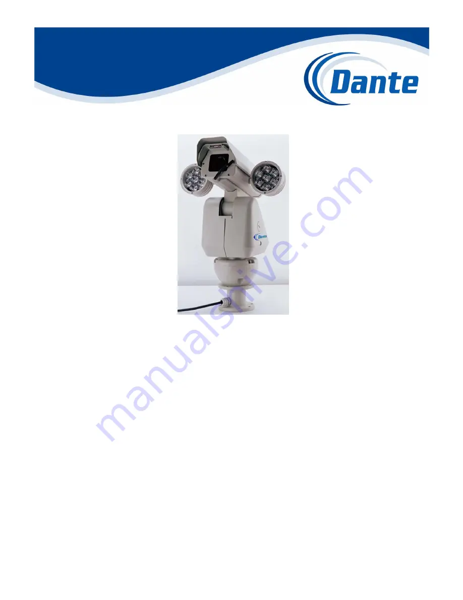
DLM1771-DLM1772(Y)-DLM1775(Y) 

Integrated Camera Positioning 


w/Optional Dual IR Lamps   


Installation and Operations Manual 


          Model Number: DLM1771, DLM1772, DLM1775,         

                                          DLM1772Y, DLM1775Y 


          Description: Integrated Camera Positioning System 

                                    with optional dual IR Lamps, Heater,       

                                    Wiper and Day/Night 18x, 23x, 26x, 30x,   

                                                                                35x and 36x Zoom     


Summary of Contents for DLM1771

Page 1: ...ng w Optional Dual IR Lamps Installation and Operations Manual Model Number DLM1771 DLM1772 DLM1775 DLM1772Y DLM1775Y Description Integrated Camera Positioning System with optional dual IR Lamps Heate...

Page 2: ...4 4 Camera parameters 19 4 5 IR Lamp Parameters 20 5 Operation 22 5 1 Basic Descriptions 22 5 2 Operation Procedures 23 5 3 Preset Functions 24 5 4 Screen Character Display 24 5 5 PTZ Functions 25 5 6...

Page 3: ...e following harsh conditions such as high wind power wide changing temperature conditions high electromagnetism and lightning and continuous operating conditions This series integrated positioning sys...

Page 4: ...tor driving stable operation sensitive reaction and accurate orientation Includes built in function menu to set camera and pan tilt parameters Features video freeze back light compensation function Pa...

Page 5: ...ontinue to hold the joystick in the down position Once you let go of the joystick after the dome rotates joystick control returns to normal operation The auto flip function is useful for following a p...

Page 6: ...round and adjust the brightness background to avoid the image full of brightness and get clear image Too strong backlight may make the object illegibility WDR Wide Dynamic Range If there is quite dark...

Page 7: ...ccessories 5 Preparation of cable Use video cable according to transmitting distance Specification of video coaxial cable features a 75 ohm resistance b copper core cable c 95 copper shield 2 3 INSTAL...

Page 8: ...all parts are present 3 1 1 Equipment List Integrated pan tilt Power Supply Box Pedestal mount Integrated pan tilt 1 pc pedestal 1 pc wall bracket 1 pc connecting cables 1 pc fixed spanner 1 pc pedest...

Page 9: ...STRUCTIONS STEP 1 Locate the floor or impending base level that may support 4 times the weight of pan tilt Fix the screws provided on the floor or firm surface STEP 2 fix the pedestal on the floor or...

Page 10: ...gs and connect them to the corresponding power supply video RS 485 wiring of the cable provided Connect the cable according to the following pinout diagram STEP 4 Fix the four 5x10 fixed screws on the...

Page 11: ...crew the nut cover tightly after completion of settings STEP 6 Turn on the power to check operation Dimensional Drawing unit MM DLM177x Pedestal Mount Inverted View of mount Maximum Bearing Weight 100...

Page 12: ...DLM177x Pedestal Mount...

Page 13: ...arts are present 3 2 1 Equipment List Integrated Pan Tilt Wall Bracket Power Supply Box Integrated pan tilt 1 pc pedestal 1 pc wall bracket 1 pc connecting cables 1 pc fixed spanner 1 pc pedestal wate...

Page 14: ...ws on the wall refer to the following picture STEP 2 Install the power supply box on the wall if power supply box is required then install the wall bracket on the power supply box If no power supply e...

Page 15: ...onding power supply video RS 485 wiring of the cable provided Connect the cable according to the following pinout diagram STEP 4 Connect the cables Connect the cables from the platform wih the power s...

Page 16: ...ew nut cover on the pan tilt s left side to expose the 8 DIP switch Set the protocol baud rate address for the pan tilt Screw the nut cover tightly after completion of settings STEP 6 Turn on the powe...

Page 17: ...top bear standard Load weight 5Kg Shield module with housing defrost device heater and fans installation wall mount pedestal mount bracket requirement 4 times of the pan tilt s weight operating tempe...

Page 18: ...ps Installation dimensions with LED IR Lamps Installation dimensions with Laser IR Lamps front view dimensions w IR LED side view dimension diagram front view dimensions w IR Laser side view dimension...

Page 19: ...nual operation Tilt 0 1 80 Second manual operation Preset speed Pan 80 Second Tilt 40 Second 4 3 Electrical parameters Input voltage 18VAC 24VDC 230VAC 50 60Hz Input power 50W 70W with IR Lamp Coaxial...

Page 20: ...NTSC PAL NTSC PAL NTSC PAL NTSC PAL Video Output 1V p p sync negative 1V p p sync negative 1V p p sync negative 1V p p sync negative Lens 26X SONY 30X Hitachi WDR Image Stabilizer 35X Hitachi WDR Ima...

Page 21: ...l start working when it is less than 1LUX Use the preset 76 to close the IR lamps Method of operation 3 Press 2 ON to open the IR lamps and the IR lamps will start working when it is less than 1LUX Pr...

Page 22: ...ars if the user does not set the POWER UP DONE the initial screen information will be seen until the camera receives the control command then the initial screen will disappear and show the system comm...

Page 23: ...type DLH4400E features RS 422 RS 485 Data PTZ control ports 3 To control via computer software press the direction key of control the camera will rotate to the operating direction The speed depends on...

Page 24: ...position 1 to 2 Alarm input 33 180 flip 34 lever home place 65 Start Washer Wiper 75 Open the IR lamps 76 Close the IR lamps 77 Open wiper function 78 Close wiper function 79 Open Digital zoom 80 Clos...

Page 25: ...ain speed on the horizontal lever 5 6 4 Installation mode The camera may be installed upwards or upside down according to requirements The image will always be showed positive on the monitor no matter...

Page 26: ...control lens zoom 5 6 11 Auto iris function The camera automatically adjusts iris to keep normal brightness in auto iris mode Manually operate OPEN or CLOSE iris adjustment button may also adjust iris...

Page 27: ...ion No 95 to open the main menu For other protocols please refer to protocol instruction The basic operation of the menu includes move menu bar enter next menu turn back to previous menu change settin...

Page 28: ...t only display in the menu 6 4 CAMERA MENU I AUTO FOCUS ZOOM LIMIT ZOOM SPEED SHARPNESS LEVEL BACKLIGHT COMP VIDEO FREEZE DAY NIGHT MODE NEXT BACK PAN TILT CAMERA SYSTEM INFORMATION CAMERA PAN TITL PO...

Page 29: ...EO FREEZE Default Setting OFF Video Freeze Mode ON and OFF DAY NIGHT Default Setting AUTO Day Night Mode Auto change Day pure color Night pure black white 6 5 CAMERA MENU II AUTO IRIS AUTO IRIS LEVEL...

Page 30: ...lected B GAIN Defaulting Setting 157 When auto white balance is under manual control 0 255 may be selected 6 6 PAN TILT MENU AUTO FLIP PROPORTIONAL PAN PARK ACTION PARK TIME PRESET TOUR TIME SCAN SPEE...

Page 31: ...ing ON Angle Display Mode ON and OFF orientation of P T and camera zoom may display when it is ON SET COORDINATES ZERO Turn the camera to the position that would be defined to be COORDINATES zero at f...

Page 32: ...f the centerline PRIVACY NO default setting is 1 Privacy No is available from 1 24 24 privacy zones may be set and most 8 privacy zones set at each image SET DISPLAY default setting is OFF Set display...

Page 33: ...When it is ON and the camera is in 1x optical zoom the privacy zone will not be shown All will appear when the camera is above 1x optical zoom When it is OFF all the privacy will be shown no matter wh...

Page 34: ...y using 1 ON 2 ON 3 ON and closed by using 1 OFF 2 OFF 3 OFF LINKAGE TIME Washer Wiper default setting is 5sec 5s 10s 15s 20s 25s 30s are selectable The wiper will run another 5s based on the selected...

Page 35: ...will run for 15 min and stop after that or by using 78 preset or by press 1 OFF Cycle startup mode use PRESET 77 or press 1 ON or set in the AUX menu and choose cycle startup mode function it only con...

Page 36: ...arthest end of pan tilt camera in order to ensure the normal work of control signal 7 2 Switch setting for SW1 Note Switch SW1 is used to set protocol camera and baud rate SW1 setting Protocol camera...

Page 37: ...FF 12 ON ON OFF ON OFF OFF OFF OFF 13 OFF OFF ON ON OFF OFF OFF OFF 14 ON OFF ON ON OFF OFF OFF OFF 15 OFF ON ON ON OFF OFF OFF OFF 16 ON ON ON ON OFF OFF OFF OFF 17 OFF OFF OFF OFF ON OFF OFF OFF 18...

Page 38: ...OFF ON ON OFF OFF OFF OFF 14 OFF ON ON ON OFF OFF OFF OFF 15 ON ON ON ON OFF OFF OFF OFF 16 OFF OFF OFF OFF ON OFF OFF OFF 17 ON OFF OFF OFF ON OFF OFF OFF 18 OFF ON OFF OFF ON OFF OFF OFF 19 ON ON O...

Page 39: ...nter the menu to reset the camera Problem the color to black white function in camera does not change Rotate control to other angle and see if condition changes If not reset camera parameter 2 PTZ Con...

Page 40: ...r power on The supply voltage is too low or the power is not enough The matching transformer of 3 5A 24VDC if VDC was specified is recommended The installation distance should be no more than 30m 3 In...

Reviews: