6280 TouchCenter Keypads
Installation Guide
Ê800-07600V3ÀÀÀ%Š
800-07600V3 4/13 Rev. C
For Online Support visit: http://www.security.honeywell.com/hsc/resources/MyWebTech/
General Information 6280 TouchCenter
This guide provides information on installing and setting up Honeywell's 6280 TouchCenter
™ Keypads. The 6280
Series graphical touch-screen keypads are Advanced User Interface (AUI) devices, which combine control of your
security system, multi-media and premises lighting.
Software Information
: To check the latest software information, press the Setup and System Info icons; the latest
Software Version is displayed.
Compatibility:
For a list of alarm systems that the TouchCenter can interface with, refer to the Compatibility Table
in this document.
Wiring
IMPORTANT
: If you power the TouchCenter from your panel’s auxiliary power output, check your panel’s
Installation and Setup Guide and verify that this device and others do not exceed your panel’s auxiliary power output
capability; if it does, a supplementary power supply is needed.
Word List
The 6280 TouchCenter can annunciate a series of words. You must use the vocabulary list in your alarm panel
instructions for actual words that may be annunciated.
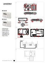
Front Panel LEDs
6280-001-V0
FLASHING
– The system contains new
message(s) for the User.
OFF
– No new messages.
RESET BUTTON
Press to reset keypad
ON
– System is armed.
OFF
– System is not armed.
ARMED (RED) LED
READY (GREEN) LED
ON
– System is disarmed and ready to arm.
OFF
– System is armed or disarmed but not
ready. If disarmed, faults or troubles are present.
MESSAGE (YELLOW) LED
SD/SDHC CARD Slot
Mounting the TouchCenter
This Keypad is for indoor use only and should be mounted at a comfortable viewing level. Avoid mounting in areas of
high condensation such as bathrooms or in locations where bright light or sunlight shines directly on the screen. The
TouchCenter can be mounted with or without the mounting plate. Use the center securing screw for European installation.
The 6280 complies with the European Standard
EN50131 and is designed to prevent unauthorized use.
Standard Mounting with mounting plate:
1. Select a mounting location.
2.
Detach the mounting plate by sliding downward.
3. Use the mounting plate to mark the location of the mounting
holes on the mounting surface and check for level.
4. Locate the mounting plate over the mounting surface such that
the wire/cable access openings are aligned while passing the
wires/cable through the case back.
***
Go to “Wiring the TouchCenter” and complete wiring***
5. Secure the mounting plate to mounting surface using 4 screws
(supplied)
.
6. Slide TouchCenter onto mounting plate.
Mounting without mounting plate:
1. Select a mounting location.
2. Detach the mounting plate by sliding downward and
discard.
3.
Use the template (provided in the carton) to mark the
location of the mounting screws and the cut-out for the
TouchCenter assembly on the mounting location. Check
for level.
4. Install 4 screws (supplied)
in the mounting surface
leaving screw heads 1/8” above the mounting surface.
5. Locate the case back over the mounting surface such
that the opening is aligned with the wire/cable access
opening on the mounting surface while passing the
wires/cable through the opening in the case back.
**
Go to “Wiring the TouchCenter” and complete wiring
6. Mount TouchCenter by sliding onto the screw heads.
4 - 3/4"
3 - 9/16"
800-08831 5/11 Re
v.A
CUT
-OUT LOCA
TION
DRILL 3/16" DIA.
HOLES
4 PLA
CES
Ê80
0-0
083
1uŠ
6280 SERIES CASE B
ACK MOUNTING
TEMPLA
TE
DRILL 3/16" DIA.
HOLE
6280-016-V0
MOUNTING
SCREWS
INSTALLED
1/8” ABOVE
SURFACE
TEMPLATE
WALL
SURFACE
Mounting (European Installations) using a center securing
screw:
1. Detach case front by removing the two bottom screws. Gently pull
up using a screwdriver if necessary and pry apart. Lift off cover.
2. Mount the TouchCenter in its final location, (see “Standard
Mounting” or “Mounting without the mounting plate”) install center
securing screw (supplied) and tighten to mounting surface.
3. Replace the case front and secure using the two bottom screws.
Note:
The European mounting procedure has not been evaluated by
UL.
6280-015-V0
INSTALL CENTER
SECURING SCREW
DETACH CASE FRONT
BY REMOVING SCREWS (2)
AND LIFT UP
CASE
FRONT
CASE
BACK
6280-006-V1
WALL
SURFACE
WALL
MOUNTING
PLATE
(OPTIONAL)
MOUNTING
SCREWS (4)
(TYP)
Wiring the TouchCenter
6280-014-V1
BLACK
POWER FROM SUPPLEMENTARY
POWER SUPPLY IF USED
6280
RED
BLACK
GREEN
YELLOW
CONTROL
TERMINAL STRIP
SUPPLEMENTARY
+12 VDC
POWER SUPPLY
P/N AD12612
BLACK (GND)
RED (+12VDC)
GREEN
(DATA TO
CONTROL)
YELLOW
(DATA FROM
CONTROL)
CONTROL
TERMINAL STRIP
AUX
DATA
IN
DATA
OUT
AUX
DATA
IN
DATA
OUT
AUX AUX
Y
G
Note:
Unshielded 4-conductor cable is recommended for the power/data wire.
UL
Use a UL Listed, battery-backed supply for UL installations. The battery supplies power to these keypads in case of AC power loss. The battery-backed power supply should
have enough power to supply the keypads with the UL required minimum standby power time.
IMPORTANT:
Keypads powered from supplies that do not have a backup battery do not function if AC power is lost. Make sure to power at least one keypad in each
partition from the control’s auxiliary power output or UL Listed battery backed up power supply.
IMPORTANT:
When the TouchCenter is powered from an auxiliary power supply, always apply power to the control panel first and then the TouchCenter. Failure to observe this
sequence results in improper operation of the TouchCenter and may result in an ECP Error indication.
Note:
Supplementary external power supply must be Listed to UL 603 for UL installations, CAN/ULC-S318 for cUL installations, and capable of providing the required backup power.
Connect the wires to the TouchCenter terminal block as shown.
•
Connect the TouchCenter in parallel with keypads and other peripheral devices using the keypad data (ECP) bus.
•
If the TouchCenter is used as the primary system keypad, maximum wire run length is 150 feet.
•
If more than one keypad is wired to one run, then the maximum lengths must be divided by the number of keypads on the run. (e.g., the maximum length is 75 feet if two keypads are
wired on a #22 gauge run).
•
DO NOT use several hardwired motion detectors in high traffic locations.
Mechanical Specifications:
Width: 8.23 inches (209.04mm)
Height: 5.59 inches (141.99mm)
Depth:1.13 inches (28.70mm)
Electrical Specifications: 9.6VDC
12VDC
13.8VDC
Backlight OFF, Sound OFF
170mA
140mA
125mA
Backlight ON, Sound OFF
270mA
215mA
190mA
Backlight ON, Sound ON
325mA
255mA
230mA
Operating Environment:
Humidity
93% RH, non-condensing
Temperature:
Operating
:
14˚ F to 131˚ F / -10˚ C to 55˚ C
(UL tested 32˚-120˚F / 0 to 49˚C)
Shipping / Storage
-40˚ F to 158˚ F / -40˚C to 70˚C
Wire Gauge:
Length
#22 gauge
150 feet
#20 gauge
240 feet
#18 gauge
350 feet
#16 gauge
550 feet
Initial Setup
Programming the Control Panel
The TouchCenter is not fully operational unless its address in the control panel
has been enabled (set as an alpha console) AUI type device, and assigned to a
partition (where applicable).
We recommend that you use either a standard alpha keypad or the TouchCenter in
Console Emulation Mode when programming the control panel. When in the
Console Mode, the TouchCenter emulates an alpha keypad and the programming
of the panel is performed following the procedures provided in your panel’s
Installation & Setup Guide.
Notes:
1. DO NOT perform panel programming while in the Safe Mode.
2. When programming your control panel, if you change the zone types for your
emergency zones you may disable the emergency buttons in the TouchCenter. The
emergency buttons in the TouchCenter are active for zone types 06 (Silent Panic
Button) and 07 (Panic Button), 08 (Medical Button), and 09 (Fire Button).
Additionally, the Medical Button is also compatible with a zone type 15 (24-Hour
Medical) for panels that contain this zone type.
Note:
Medical functionality has not been evaluated by UL and may not be used in
UL Listed applications.
The TouchCenter should not be assigned as a Master Console. If the TouchCenter
is assigned as a Master Console, partitions must be controlled from the Partition
screen or by using the Console Emulation Mode.
TouchCenter Initialization
When initially powered, the screen displays the boot sequence and the "Set ECP
Address" screen is displayed. If the system is incorporating only one TouchCenter,
leave the address set to 1 and touch
Apply
. The boot-up process continues until
completion. If there are to be additional TouchCenter units in the system, after
enabling addresses in the control panel using an alpha-keypad, power-up each
TouchCenter one at a time, and set its address to one of the addresses you enabled
in the control panel.
Note:
If the top of the screen is displaying ECP Error, the TouchCenter ECP
Address is not valid for the panel that it is connected to. To change the ECP
Address, enter the default code of “4140” to advance to the next screen.
Note:
4140 is the TouchCenter default installer code before connecting to a control
panel. Once connected to a control panel, use the panel’s installer code.
Change the ECP Address on the unit, using the Up/Down arrows and then touch
apply to accept the address and reset the TouchCenter. Once communication has
been restored, then use the standard panel installer code for all installer functions.
Refer to “ECP Setup” section.
Language Sélection
After initial ECP selection is set, the « Languages » menu is displayed. Select from
English, French Canadian and Latin American Spanish.
Installer Note:
The 6280 Touch Screen has been calibrated at the factory. Ignore
the “CALIBRATE” button that appears on the “Options” screen after initial ECP
setup. If the screen should require recalibration, do so via the “Keypad Test” screen.
See the “Diagnostic Tests” section for instructions.
Time/Date Setup
If not already set from the panel, set the current time and date. Refer to
“Time/Date Setup” section.
NIGHT Setup
The TouchCenter is defaulted to arm the system in the STAY INSTANT mode
when arming the system using the NIGHT icon.
Select the arming mode to be activated when the
NIGHT
icon is touched on the
"Arming" screen, refer to “Night Setup” section.