background image

Introduction

Installation and 

Connection

Direct Remote 

Control Function

Configuration via 

Menus Function

Appendix

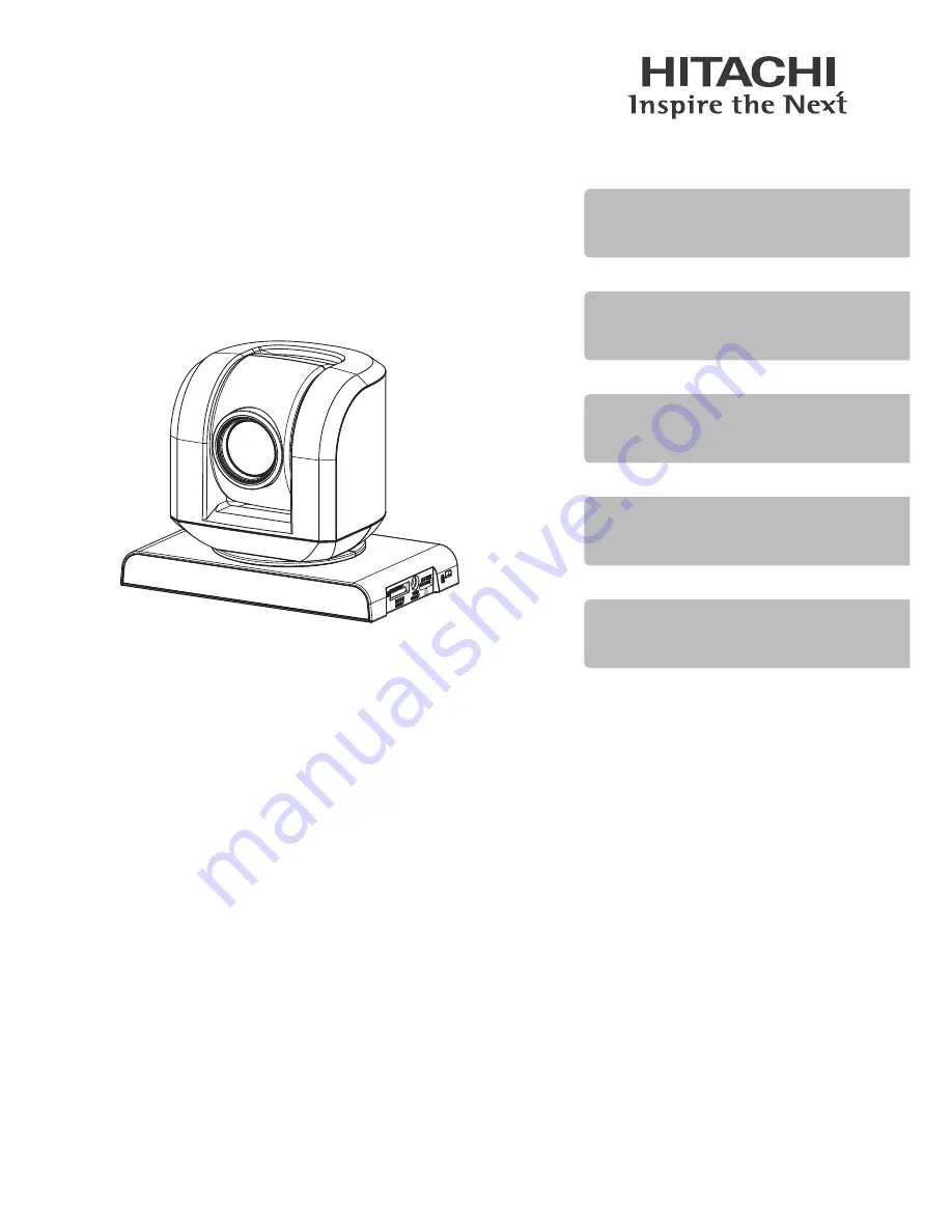
Thank you for purchasing this Hitachi camera.

Please read this User's Manual thoroughly and use the camera as instructed.

After reading the User's Manual, store it safely.

User’s Manual

VZ-HD4000A

VZ-HD4900A

Summary of Contents for VZ-HD4000A

Page 1: ...trol Function Configuration via Menus Function Appendix Thank you for purchasing this Hitachi camera Please read this User s Manual thoroughly and use the camera as instructed After reading the User s Manual store it safely User s Manual VZ HD4000A VZ HD4900A ...

Page 2: ...ICEABLE PARTS INSIDE REFER SERVICING TO QUALIFIED SERVICE PERSONNEL Identifications of caution marks This symbol warns the user that uninsulated voltage within the unit may have sufficient magnitude to cause electric shock Therefore it is dangerous to make any kind of contact with any inside part of this unit This symbol alerts the user that important literature concerning the operation and mainte...

Page 3: ...ding amplifiers 9 Protect the power cable and cord from being stepped on or pinched particularly at the plugs power outlets and where it connects to the camera 10 Only use the attachments and accessories specified by the manufacturer 11 Use the camera only with a cart stand tripod bracket or table specified by the manufacturer or sold with the camera When using a cart to move the camera use cautio...

Page 4: ...e of this camera is too high or too low normal image output may not be possible Be careful of moisture condensation When you move the camera between places where the difference in temperatures is great condensation vapor in air warmed or cooled to water droplets could occur on the lens and or inside the camera If condensation occurs on the lens wipe it off with a soft dry cloth Even if the externa...

Page 5: ...a Do not use benzene or thinner to clean the surface of the camera The coating of the case could peel off or the case could deteriorate Wipe off dirt on the case with a dry soft cloth which has been completely wrung out When using a chemical cleaning cloth follow instructions for use l Warnings about Transport This camera is a precision device Transporting the device without using the packing mate...

Page 6: ... are designed to provide reasonable protection against harmful interference when the equipment is operated in a commercial environment This equipment generates uses and can radiate radio frequency energy and if not installed and used in accordance with the instruction manual may cause harmful interference to radio communications Operation of this equipment in a residential area is likely to cause ...

Page 7: ...a Monitor with an Analog RGB IN Terminal 23 Connecting to a Monitor with a DVI IN Terminal 24 Connecting to a Monitor with an HD SDI IN Terminal 24 Connecting to a Monitor with a 3G SDI IN Terminal 25 Connecting to an External Device with an RS 232C 25 Connecting Multiple Cameras to an External Device 26 Direct Remote Control Function 28 Before Use 28 Selecting Remote Control Codes 28 Turning the ...

Page 8: ...oise NR Setup 44 Swivel Setup 45 Reversing Pan Tilt Movement 45 Limiting the Pan Tilt Range 45 Setting the Pan Tilt Speed 45 Initial Setup 46 Setting the Output Format Color System 46 Reverting All Menu Settings to their Initial Setup Reset 46 Appendix 47 Troubleshooting 47 Menu Structure 51 Preset Items and Retained Settings 53 Software License Information 54 Main Specifications 60 Dimensional Dr...

Page 9: ...ds The VZ HD4900A has a standard video output DVI I interface as well as the latest 3G SDI interface and it supports both digital and analog video output at 1080p 59 94 or 1080p 50 3G SDI complies with SMPTE424M serial digital interface standards Pan Tilt Mechanism A direct drive motor powers the pan tilt mechanism which allows quick and quiet pan tilt operation Equipped with 32 Presets The system...

Page 10: ...d Connects the AC adapter to an outlet Remote control RS 422 terminal block connector Used to make a connection cable when using RS 422 Two AAA batteries For the remote control Three M5 12 screws Four M3 8 screws Ceiling mount fixture Camera side Ceiling mount fixture Ceiling side Safety wire Front panel for desktop installation Front panel for ceiling installation ...

Page 11: ... making cables refer to the wiring diagrams on page 64 for pin layout and page 65 for the wiring diagram of RS 422 cables Also refer to page 66 for how to use RS 422 terminal block connector Getting the Remote Control Ready Caution Warnings about Using Dry Cell Batteries Do not use any batteries in this device except those specified Also do not mix old and new batteries Doing so may cause fire or ...

Page 12: ... 28 STANDBY lamp P 28 Remote receiver IR sensor P 28 42 SYSTEM SELECT switch P 15 VIDEO SELECT switch P 14 EXT SLOT This is an extension slot for maintenance and is not normally used Anti theft lock installation hole Use a theft prevention cable sold separately ...

Page 13: ...2V terminal P 22 RS 232C IN terminal P 25 RS 232C OUT terminal P 26 RS 422 terminal P 26 VIDEO OUT DVI I terminal VZ HD4900A P 23 VIDEO OUT HD SDI terminal VZ HD4000A P 24 VIDEO OUT 3G SDI terminal VZ HD4900A P 25 Tripod mounting hole P 19 Screw mounting holes P 19 Rating label ...

Page 14: ...onfigure the setting so it matches the monitor s resolution The Hi Vision video signal outputs a distortion free image on monitors with an 16 9 aspect ratio Set it to the desired video format Switch position Video output format 0 1080i 59 94 1 1080p 59 94 VZ HD4900A 2 720p 59 94 3 1080p 29 97 4 5 6 7 Serial control 8 1080i 50 9 1080p 50 VZ HD4900A A 720p 50 B 1080p 25 C D E F This is the factory d...

Page 15: ... to Analog Horizontal Sync Analog Vertical Sync OFF Does not add Sync ON Adds Sync Switch 4 Not used VZ HD4000A Always set to ON Switch 5 Not used Always set to OFF Switch 6 Not used Always set to OFF Switches 7 9 remote code switch Allows you to select the remote control code RC 1 to RC 3 to receive in cases such as when operating multiple cameras with the same remote or to avoid interference fro...

Page 16: ...d prior to turning the camera on Do not make these settings after turning the power on If you switch the setting for the installation method and then turn the power on it will erase all the presets When connecting devices in a daisy chain P 26 it is necessary to make the Serial communication baud rate and RS 232C RS 422 selections the same for all connected cameras To change switch settings use a ...

Page 17: ...POSURE Button P 33 10 key Buttons for presets P 35 PRESET Button P 35 HOME Button P 31 TELE WIDE Buttons P 31 MENU Button P 37 BACK Button P 38 POWER Button P 28 FULL AUTO Button P 34 RESET Button P 35 Buttons P 32 33 DIGITAL ZOOM Button P 32 DISPLAY Button P 29 Cursor Buttons ENTER Button P 31 37 38 BLC Backlight compensation Button P 34 ...

Page 18: ...ethod selection to ON ceiling installation P 15 Caution During installation take steps as needed to prevent the camera from falling Install the camera so it is level Install it in a normal orientation Desktop Installation Ceiling Installation When moving the device hold the head of the camera in a fixed position with both hands and carry the device by the base Do not simply carry it by its base or...

Page 19: ...ndard size of usable tripod mounting screw 20UNC 4 5 mm 0 2 mm Caution Set up the tripod according to its user s manual so it is steady and will not fall over Warning Do not mount the camera using the tripod screw when installing it in a high place Install with Mounting Screws Sold Separately Install mounting screws in the four screw mounting holes on the base Tighten the 4 screws securely Screw m...

Page 20: ... least 20kg and then mount the camera securely If materials are not strong enough it may fall and cause an injury To prevent it from falling be sure to attach the safety wire Take all due care to prevent the camera from falling during installation If installed in a high place inspect once a year to make sure the mount has not become loose Make more frequent inspections if the conditions of use cal...

Page 21: ...tep 1 to the ceiling mount fixture ceiling side with the included screws M5 12 Install the mounting hardware as indicated by the mark Safety wire Included screw M5 12 Mark 5 Align the tabs A sticking up on the ceiling mount fixture camera side with ceiling mount fixture s ceiling side holes B and slide in so they are held in position Tuck the extra length of the safety wire inside the ceiling moun...

Page 22: ...To outlet To DC IN 12V terminal Caution When the power is plugged in the head of the camera will first start to move Plug the power cord in after the device is installed Do not use any power cord or AC adapter other than those provided This device does not have a power switch When installing the device either install a dedicated switch that is hardwired and easily accessible or plug the power cord...

Page 23: ...l output according to the specifications of the connected monitor or external device Connecting to a Monitor with an Analog RGB IN Terminal VZ HD4900A アナログ RGB 入力端子へ VIDEO OUT DVI I 端子へ DVI アナログ RGB 変換ケーブル HD ビデオモニターなど To VIDEO OUT DVI I terminal DVI Analog RGB converter cable To Analog RGB IN terminal HD video monitor etc See P 63 for terminal specifications Set to the video output format P 14 ou...

Page 24: ...r Sync signal P 15 of the analog video signal output according to the specifications of the connected monitor or external device Connecting to a Monitor with an HD SDI IN Terminal HD ビデオモニターなど HD SDI 入力端子へ VIDEO OUT HD SDI 3G SDI 端子へ HD SDIケーブル To VIDEO OUT HD SDI terminal HD SDI cable To HD SDI IN terminal HD video monitor etc Set the video output format P 14 according to the specifications of th...

Page 25: ...ernal device Regardless of the output format P 46 setting the 3G SDI output will be YPbPr Connecting to an External Device with an RS 232C l Use an RS 232C to connect the camera for control via an external device 1 Connect as follows with an RS 232C cable RS 232C cable RS 232C IN terminal To external device See P 63 for terminal specifications 2 Select SYSTEM SELECT SWITCH 1 serial communication b...

Page 26: ... 2 To make connections with RS 422 cables use the included RS 422 terminal block connector and make connection cables When making cables refer to the wiring diagrams on P 64 for pin layout and P 65 for the wiring diagram for RS 422 cables Also refer to P 66 for how to use RS 422 terminal block connectors 3 Select SYSTEM SELECT SWITCH 1 serial communication baud rate for the connected external devi...

Page 27: ... Camera 2 Camera 2 Camera 3 Camera 3 Caution When connecting devices in a daisy chain it is necessary to make the selections the same for all the connected cameras namely the SYSTEM SELECT SWITCH 1 serial communication baud rate and SYSTEM SELECT SWITCH 3 RS 232C RS 422 Make the switch settings before turning the device on Turn the power on after making switch settings P 28 To change SYSTEM SELECT...

Page 28: ...A on the remote control and operate the designated camera Ex To operate CAMERA1 set the SYSTEM SELECT Switches to ON OFF OFF RC1 Refer to Remote Control Indicators on P 36 for the meaning of lighted remote control indicators Turning the Power ON STANDBY lamp POWER lamp 1 Press POWER on the remote control The power comes on The POWER lamp lights and the STANDBY lamp goes off The camera automaticall...

Page 29: ... are displayed as in the following example If you press DISPLAY again the display turns off Function Direct Remote Control Operation Menu Operation Zoom P 31 Exposure P 33 Program AE P 39 White Balance P 41 BLC Backlight compensation P 34 Manual Focus P 32 Full Auto P 34 Screenshot for explanation purposes Actual displays will differ ...

Page 30: ...Maximum optical zoom Digital Zoom 300x Exposure No icon Auto Manual Program AE No icon Auto Manual Shutter Iris Spotlight White Board White Balance No icon Auto Manual Set Outdoor Indoor1 Indoor2 BLC Backlight compensation No icon Off On Manual Focus No icon Auto Manual Following are displays of settings that can be made for different functions shown by setting content Default content shown first ...

Page 31: ...e slight movements or press long to make long ones The camera cannot be panned or tilted while a menu is displayed To return the camera to its normal orientation home position press HOME Zooming The camera can zoom up to 25x optically or 300x digitally The digital zoom function is Off when purchased TELE WIDE 1 While viewing the screen press TELE or WIDE To zoom in and make the subject appear larg...

Page 32: ...hen operating zoom the focus may blur for a moment When digital zoom is added the image quality will become coarser Adjusting the Camera Adjusting the Focus Manually Manual Focus If it is difficult to adjust the focus automatically you can adjust it manually FOCUS 1 Press FOCUS It changes to manual focus mode 2 Press or to adjust the focus To focus on a distant subject press and to focus on a near...

Page 33: ...if Subjects are not in the center of the frame both near and far subjects are within the auto focus bracket at the same time subjects are moving rapidly subjects are dark or low in contrast etc Adjusting the Brightness of the Image Exposure Normally the exposure is automatically adjusted However depending on the shooting conditions the exposure can be adjusted manually EXPOSURE 1 Press EXPOSURE 2 ...

Page 34: ...results of backlight compensation are not reflected When the Program AE mode is set to anything other than Manual the results of backlight compensation are reflected Returning Changed Settings to their Defaults Full Auto The following settings can be returned to their defaults with one button Function Default Refer to Focus Auto P 32 Exposure Auto P 33 BLC Backlight compensation Off P 34 Program A...

Page 35: ...t number buttons ENTER 1 When the camera is in the state you wish to save press PRESET and then press the number you wish to save from 1 to 32 2 Press ENTER To Call up a Camera Preset Press the number of the preset 1 to 32 you wish to call up and then press ENTER To Delete a Preset Reset Press RESET and then the number of the preset 1 to 32 you wish to delete and then press ENTER Entering Numbers ...

Page 36: ...tor of the configured camera number CAMERA light up Caution While trying to save call up or delete a camera preset if you enter a number other than from 1 to 32 or if you press another button and you leave the number entered as is without pressing ENTER for a certain period of time the entry is disabled and the indicators CAMERA of the camera numbers that had been configured with a PRESET RESET go...

Page 37: ...ns of operations that can be achieved using cursor buttons are simplified ENTER MENU BACK 1 Press MENU The menu opens Adjust the white balance and select a shooting mode to match the situation Camera Functions Setup ENTER Program AE Digital Zoom White Balance EXIT Auto Off Auto Menu item on the top level its icon and description Remote control buttons that work on this screen Menu items on the 2nd...

Page 38: ... to activate it Setting items that can be selected for the chosen menu item are displayed The sample screenshot is with Digital Zoom selected and activated Camera Functions Setup Program AE Digital Zoom White Balance 300x Cancel the digital zoom 100x Off 200x RETURN ENTER To go back to menu selections on the 2nd level press BACK or 4 Use or to select the desired setting and activate it with ENTER ...

Page 39: ...r speed aperture iris are adjusted manually Shutter The shutter speed is adjusted manually Iris The aperture is adjusted manually Spotlight When a strong light is on the subject this prevents the person s face from washing out White Board Provides the ideal exposure control for shooting a white board If you select a Program AE mode new settings that can be made in the selected mode are displayed f...

Page 40: ... F2 0 F1 6 and F1 4 Gain Limit This sets the upper limit of sensitivity gain when Auto Shutter Iris Spotlight or White Board are selected It can be set in a range from 0 to 30dB 31 steps Slow Shutter This sets the minimum value of the slow shutter speed when Auto is selected When the image output format is 59 94 29 97 you can select from 1 60 1 30 or 1 15 When the image output format is 50 25 you ...

Page 41: ...ng the white balance When you wish to adjust the color you can change the white balance setting White balance mode Auto No icon appears Manual Select values for the R gain red gain and the B gain blue gain to set the white balance This can be set in a range from 128 to 127 256 steps Set You can manually adjust white balance to match the light source or situation Outdoor To shoot in fine weather In...

Page 42: ...traight ahead it may be difficult to get a good color balance Infrared sensor Setting the white balance manually Set Prepare a white object such a thick sheet of white paper that is not translucent 1 Point the camcorder at the white object so that it fills the screen Thick white paper etc 2 Press MENU 3 Select Camera Function Setup White Balance Set At this point will start blinking on the screen ...

Page 43: ...Also if the zoom bar is positioned in the digital range p 30 you may not be able to set the white balance If white balance settings cannot be accomplished will continue to flash If configuring Set is not completed and the power is turned off or a preset is saved may flash on the screen Repeat the procedure from step 1 Setting the digital zoom Although the digital zoom setting can be made using Dig...

Page 44: ...rom 0 to 79 80 steps The smaller the setting value the more intense the black level Setting the Gamma Level Gamma This allows you to set the gamma level of the image It can be set in a range from 0 to 16 17 steps The smaller the setting value the more it corrects the brightness of the intermediate level to the brighter side Reducing Noise NR Setup This allows you to reduce the level of noise in th...

Page 45: ... then specify the range for each parameter left and right edges for panning and up down edges for tilting The left and right edges can be set in a range from 175 to 175 while the top bottom limits can be set from 90 to 30 desktop installation or 30 to 90 ceiling installation and can be set in 1 increments Caution If the System Select Switch 10 installation method selection is changed the limits of...

Page 46: ...Select Initial Setup Color System RGB YPbPr 3 Press ENTER to exit the MENU Caution Regardless of the output format setting the HD SDI 3G SDI output will be YPbPr Reverting All Menu Settings to their Initial Setup Reset 1 Press MENU 2 Press Initial Setup Reset 3 Press ENTER The following screen opens Reset RETURN ENTER Reset Yes No 4 Use to select Yes and press ENTER Caution If you reset the settin...

Page 47: ...e camera been subject to a severe shock The camera may be broken Consult with the store where you purchased it When the power is plugged in the head of the camera moves around at will This is not a fault When the power is plugged in the head of the camera will first start to move It then returns to the home position automatically Do not touch the head of the camera when it is moving P 28 Pan Tilt ...

Page 48: ...e subject appears distorted This is not a fault The subject may appear slightly distorted due to the nature of the image sensor CMOS There are horizontal stripes on the screen This is not a fault It may appear this way under artificial lighting Bright spots appear on the screen This is not a fault On rare occasions bright spots may appear on dark subjects There is a green stripe on the right side ...

Page 49: ...g to shoot a subject that is hard for the autofocus to bring into focus Try focusing manually P 32 Is the camera in the manual focus mode Focus the camera manually or cancel the manual focus mode P 32 Is there a cell phone or radio nearby Move it away from the camera and turn the power on again P 4 If none of the above apply try turning the power off and back on again Communication with External D...

Page 50: ...nder a bright light such as a fluorescent one When the receiver is under a bright light it will not work Adjust the location and or the angle of the device Are there batteries in the remote control Check the batteries are facing the right way as well The batteries may be dead Replace the batteries Is the camera number the same on the camera and the remote control Set the camera number on the remot...

Page 51: ...evel Menu Item 2nd Level Setting Refer to Camera Functions Setup Program AE Auto P 38 Manual Shutter Iris Spotlight White Board White Balance Auto P 40 Manual Set Outdoor Indoor 1 Indoor 2 Digital Zoom 300x P 42 200x 100x Off Image Setup Saturation P 43 Enhancement Pedestal Gamma NR Setup ...

Page 52: ... 45 Off Tilt Reverse On Off Pan Tilt Limit On Off Speed Setup Mode 1 Mode 2 Mode 3 Mode 4 Mode 5 Initial Setup Color System VZ HD4900A RGB P 45 YPbPr Reset P 45 This is the factory default setting For information on settings when the camera starts up refer to Preset Items and Retained Settings P 53 ...

Page 53: ...et 1 is Registered Items that can be Preset Startup Settings when no Preset 1 is Registered Pan Tilt Position Home position front Zoom Position Wide end Exposure Auto Manual Exposure value Auto Focus Auto Manual Focus position Auto BLC Backlight compensation On Off Off Program AE Settings including values for each setting Auto Gain Limit 30dB Slow Shutter 59 94 29 97Hz 1 60 50 25Hz 1 50 Aperture L...

Page 54: ...r referred to as the Software License Agreement established by the Free Software Foundation Inc of the U S Refer to the following table for information on subject software modules If you have questions about subject software modules please contact the store where you purchased it For details about said software modules such as conditions of use please read the software license agreement of each so...

Page 55: ... work under the terms of Section 1 above provided that you also meet all of these conditions a You must cause the modified files to carry prominent notices stating that you changed the files and the date of any change b You must cause any work that you distribute or publish that in whole or in part contains or is derived from the Program or any part thereof to be li censed as a whole at no charge ...

Page 56: ...u wish to incorporate parts of the Program into other free programs whose distribution conditions are different write to the author to ask for permis sion For software which is copyrighted by the Free Software Foundation write to the Free Software Foundation we sometimes make exceptions for this Our decision will be guided by the two goals of preserving the free status of all deriv atives of our f...

Page 57: ...ee li braries In this case there is little to gain by limiting the free library to free soft ware only so we use the Lesser General Public License In other cases permission to use a particular library in non free programs en ables a greater number of people to use a large body of free software For exam ple permission to use the GNU C Library in non free programs enables many more people to use the...

Page 58: ...ary and its use are covered by this License You must supply a copy of this License If the work during execution displays copyright no tices you must include the copyright notice for the Library among them as well as a reference directing the user to the copy of this License Also you must do one of these things a Accompany the work with the complete corresponding machine readable source code for th...

Page 59: ...O THE EXTENT PERMITTED BY APPLICABLE LAW EXCEPT WHEN OTHERWISE STATED IN WRITING THE COPYRIGHT HOLDERS AND OR OTHER PARTIES PROVIDE THE LIBRARY AS IS WITHOUT WARRANTY OF ANY KIND EITHER EXPRESSED OR IMPLIED INCLUDING BUT NOT LIMITED TO THE IMPLIED WARRANTIES OF MERCHANTABILITY AND FITNESS FOR A PARTICULAR PURPOSE THE ENTIRE RISK AS TO THE QUAL ITY AND PERFORMANCE OF THE LIBRARY IS WITH YOU SHOULD ...

Page 60: ... 25 1080i 50 720p 50 Pan Tilt Functions Horizontal 175 Vertical 30 to 90 Desktop Installation 90 to 30 Ceiling Installation Video OUT Terminals VZ HD4000A HD SDI terminal 1 VZ HD4900A DVI I terminal 1 3G SDI terminal 1 Serial control terminal RS 232C 8 pin miniDIN terminal IN 1 OUT 1 RS 422 connect terminal block 9 pin Input Voltage DC 12V DC 11 4 to 12 6V Current Consumption at DC12V 2 5A max 1 0...

Page 61: ...61 Appendix 4 M3 1 4 20UNC Ø5 Dimensional Drawing Desktop Installation Top Front Base Unit mm Side ...

Page 62: ...62 Appendix 4 Ø5 6 hole Dimensional Drawing Ceiling Installation Base Front Bottom Unit mm Side ...

Page 63: ...Data 1 3 shield 12 TMDS Data 3 Not used 13 TMDS Data 3 Not used 14 5V 15 GND 16 Hot Plug Detect 17 TMDS data 0 Pin No Function 18 TMDS data 0 19 TMDS data 0 5 shield 20 TMDS data 5 Not used 21 TMDS data 5 Not used 22 TMDS clock shield 23 TMDS clock 24 TMDS clock C1 Analog Red Pr C2 Analog Green Y C3 Analog Blue Pb C4 Analog Horizontal Sync C5 Analog GND The analog video signal of pins C1 C2 and C3...

Page 64: ...7 can be switched with the System Select switch P 15 RS 232C OUT terminal 8 pin mini DIN female OUT Pin No Function 1 DTR OUT 2 DSR OUT 3 TxD OUT 4 GND 5 RxD OUT 6 GND 7 Not used 8 Not used RS 422 terminal connect terminal block 9 pin 1 2 3 4 5 6 7 8 9 RS 422 Pin No Function 1 RxD OUT 2 RxD OUT 3 TxD OUT 4 TxD OUT 5 GND 6 RxD IN 7 RxD IN 8 TxD IN 9 TxD IN ...

Page 65: ...9 TxD IN GND RxD OUT RxD OUT TxD OUT TxD OUT 1 RxD OUT 2 RxD OUT 3 TxD OUT 4 TxD OUT 5 GND 6 RxD IN 7 RxD IN 8 TxD IN 9 TxD IN 1 RxD OUT 2 RxD OUT 3 TxD OUT 4 TxD OUT 5 GND 6 RxD IN 7 RxD IN 8 TxD IN 9 TxD IN Camera2 RS 422 terminal Camera1 RS 422 terminal RS 422 terminal of Camera3 thereafter External device terminal ...

Page 66: ... AWG 28 18 2 Plug the RS 422 terminal block connector into the RS 422 terminal 1 2 3 4 5 6 7 8 9 RS 422 When Unplugging Connector Plugs Grasp both ends of the RS 422 terminal block connector plug and unplug it as shown in the diagram 1 2 3 4 5 6 7 8 9 RS 422 Caution In order to stabilize the voltage level of signals cross ground them When connecting via RS 422 connections via RS 232C cannot be mad...

Page 67: ...haser only and is not transferable To qualify for coverage under this Limited Warranty purchaser must notify Hitachi of a warranty claim during the Limited Warranty Period by calling 800 HITACHI and must provide a dated sales receipt for the Product PARTS AND LABOR There will be no charge for any replacement parts or labor required to correct a qualifying defect that arises during the Limited Warr...

Page 68: ...chi or any Hitachi designated facility for repair or replacement that is attributable to improper packaging mishandling or shipping by Purchaser m any Product purchased or serviced outside the United States including Puerto Rico or n any Product purchased in non new or non factory sealed condition such as in AS IS refurbished reconditioned or previously owned condition or any other similar conditi...

Page 69: ...69 ...

Page 70: ...70 ...

Page 71: ...71 ...

Page 72: ...QR85801 Hitachi Industry Control Solutions Ltd 2015 Printed in Japan I ...

Reviews: