
Quick Installation Guide
2.5 inch Hard Disk Drives ATA/IDE
Handling Precautions
1. Do not press on the drive. Hold the drive by the sides only, do not apply any
force to the drive during handling or installation
2. Always handle the drive with care to prevent damage from shock, vibration or
electrostatic discharge (ESD). Do not touch the Printed Circuit Board (PCB).
3. Electrostatic Discharge. Static electricity can damage the drive. Before handling
the drive, touch an unpainted metal surface for a few seconds to drain any static
electricity from your body.
4. Keep the original packaging and static-protective bag in case the drive has to
be returned.
Quick Installation Procedure
It is advisable to backup all data before proceeding with the installation. If your
system BIOS cannot handle large capacity drives (over 540MB, or 8.4GB) you
may need to use a disk overlay program such as Ontrack’s Disk Manager
software. Contact your Hitachi supplier or the local Hitachi office.
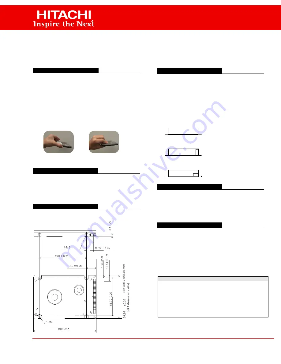
Dimensions / Screw Locations
Check that the dimensions and screw hole locations are correct
for your system.
Setting the Jumpers
1. In a one drive system configure the new drive as a Master with no jumpers
attached.
2. In a two drive system, one drive must be designated as Master and the other
as Slave.
3. When installing the new drive as a Slave set the jumper to position A-B. Check
the Master drive to determine if a jumper change is required to indicate Slave
present.
4. Before selecting Cable Select (CSEL D-B) consult your system manual to see
if this is supported.
Attaching the Drive
1. Turn off the computer, unplug the power cord and remove the notebook battery.
2. Open the cover.
3. Match pin 1 of the 44 pin cable, usually denoted by a red stripe, to pin 1 of the
drive interface connector, shown above.
4. Mount the drive securely using 4 M3 (metric) screws with a maximum screw
length of 2.5 mm.
Configuring your Computer
1. Reinstall the notebook battery, plug in the power cord and turn on the computer.
2. The computer may detect a configuration change and prompt you to proceed to
the Setup screen.
3. If it does not, enter the Setup screen using the key selection. Refer to the
onscreen instructions or the computer handbook.
4. Select “Auto Detect” for the new drive, if your system supports this feature. If it
does not , select the “User Definable Type” and enter the parameters from the
table below.
5. If you cannot see the full capacity of the drive use Disk Manager.
6. Partition and Format the drive, then install your data.
If, after complete installation, your system will not boot up, recheck all settings. If
the system still fails to boot up, contact your supplier’s technical support.
ü
X
correct
incorrect
O - - - - - - - - O O O O O
O - - - - - - - - O O O O O
43
5 3 1
C A
44
6 4 2
D B
O - - - - - - - - O O O O O
O - - - - - - - - O O O O O
43
5 3 1
C A
44
6 4 2
D B
O - - - - - - - - O O O O O
O - - - - - - - - O O O O O
43
5 3 1
C A
44
6 4 2
D B
1) DRIVE 0 (or Master)
2) DRIVE 1 (or Slave)
3) CSEL Selection
If all of pins A,B,
D are open, the drive is
DRIVE 0(or Master).
If jumper Position A-B is used, the drive is
DRIVE 1 (or Slave).
If jumper Position A-C is used, DRIVE 0 or
DRIVE 1 setting is determined by the condition of
CSEL signal (pin# 28).
© The statements in this publication are not intended to create any warranty, expressed
or implied. Specifications and product offerings subject to change without notice.
All product names and logos are trademarks of their respective owners.
For sales information on Hitachi products: 1-800-HITACHI (1-800-448-2244)
Web Site: http://www.hitachi.com/storage
0.0
0.2
0.4
0.6
0.8
1.0
DK237A -21, DK237A-32, DK238A-32, DK238A-43, DK239A-48,
DK239A-65, DK23AA-60, DK23AA-90, DK23AA-12, DK23BA,
DK23CA -xx, DK23DA-xx and later
Model
Cylinders Heads
Sectors
LZ
WPC
Capacity
DK237A-21 4200
16
63
4200
4200
2.1GB
DK237A-32 6304
16
63
6304
6304
3.2GB
DK238A-32 6304
16
63
6304
6304
3.2GB
DK238A-43 8944
15
63
8944
8944
4.3GB
DK239A-48 10068
15
63
10068
10068
4.8GB
DK239A-65 13424
15
63
13424
13424
6.5GB
DK23AA-60 12416
15
63
12416
12416
6GB
All Others
16383
16
63
16383
16383
8.4GB+*
* Maximum
addressable capacity in CHS mode is 8.455 GB


