Hitachi DC 120VA, Technical Data And Service Manual
The Hitachi DC 120VA comes with a comprehensive Handling Instructions Manual that is essential for understanding and effectively using this product. You can easily access and download the free manual from our website, ensuring a hassle-free ownership experience. Visit manualshive.com to get your hands on this valuable resource.
Share
Download


Reviews:
No comments
Related manuals for DC 120VA

SS48055 LP
Brand: Patio Chef Pages: 34

EZT40050-P340
Brand: Fiesta Pages: 13

ProPress 2160
Brand: Villaware Pages: 10

PCC620
Brand: Porter-Cable Pages: 40

ADELAIDE PLANCHA TTL
Brand: Campingaz Pages: 69

PBL2022P
Brand: stayer Pages: 52

Grillerette Pro
Brand: TABLETOP Chefs Pages: 14

58828TS
Brand: Red Stone Pages: 25

Health Smart Grill Pro 42514
Brand: Gastroback Pages: 20

GRI 660
Brand: Gallet Pages: 52

DB 10
Brand: Metabo Pages: 52

112402
Brand: Princess Pages: 52

BG179A
Brand: Master Forge Pages: 38

XPH12T
Brand: Makita Pages: 11

NUEVO XT296ST
Brand: Makita Pages: 28

HP488D006
Brand: Makita Pages: 68

GBC983W-C
Brand: Uniflame Pages: 24
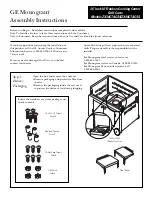
ZX48CTACSS
Brand: GE Pages: 4


