

AV FOR AN IT WORLD
®
QUICK START GUIDE
MD-702
7” Modero G5 Wall Mount Touch Panel
Overview
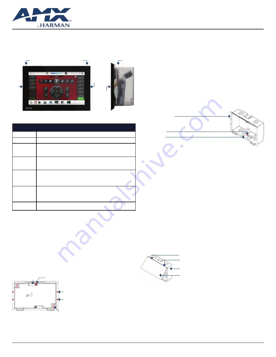
The MD-702 (FG5969-55BL) 7” Modero G5 Wall Mount Touch Panel features
the G5 Graphics Engine, Quad Core Processor, and a capacitive multi-touch
display. This panel now supports two operational modes: as a customizable
Modero panel to be configured with RPM or TPDesign5/Netlinx Studio, or as
an Acendo Book scheduling panel which connects directly to popular room
scheduling software.
Sleep button
Backbox
Optional Microphone
Left
LED
Side
LED
Right
LED
(side view)
FIG. 1
MD-702
Product Specifications
MD-702 SPECIFICATIONS
Dimensions (HWD)
4 7/8” x 7 3/8” x 2 1/4” (123.9mm x 187.5mm x 58mm), with Backbox
Weight
1.05 lbs (.680 Kg), with Backbox / 0.8 lbs (.363 Kg), without Backbox
Power
Consumption
• Full-On: 14.5W maximum
• Standby: 5.8W
• Shutdown: 1W
• Start-Up Inrush Current: Not applicable due to PoE standard
External Power
Supply Required
Optimal performance requires use of one of the following AMX PoE power supplies (not
included):
• PS-POE-AT-TC, PoE Injector, 802.3AT Compliant (FG423-84)
• NXA-ENET8-POE+, Gigabit PoE Ethernet Switch (FG2178-64)
Certifications
• FCC Part 15 Class B
• AUS/NZ
• EN 55032:2012/AC:2013 Class B
• CISPR32:2015
• IEC/EN-60950
• KN32 Class B
• CAN-ICES-3(B)/NMB-3(B)
• UL 60950-1
• RoHS/WEEE compliant
Environmental
• Temperature (Operating): 32°F to 104°F (0°C to 40°C)
• Temperature (Storage): 4°F to 140°F (-20°C to 60°C)
• Humidity (Operating): 20% to 85% RH
• Humidity (Storage): 5% to 85% RH
• Power (“Heat”) Dissipation: On: 49.5 BTU/hr, Standby: 19.8 BTU/hr
Included
Accessories
• Installation Template, 7” Wall Mount (68-2265-02)
• Backbox, Wall Mount, 7” (5095917-00)
MD-702 Installation
The MD-702 can be installed via several mounting options: Use the included
clear plastic Backbox to attach the panel to most standard wall materials. Other
optional AMX mounting solutions include the MSA-MMK2-07 Multi Mount Kit, the
MSA-AMK2-07 Any Mount Kit, CB-MXSA-07 Rough-In Box and the MSA-RMK-07
Rack Mount Kit. Refer to the Quick Start Guide included with each mounting kit
for instructions.
Power Over Ethernet
Power for the MD-702 is supplied via Power Over Ethernet (PoE), utilizing an
AMXcertified PoE injector such as the PS-POE-AT-TC, PoE Injector, 802.3AT Compliant
(FG423-84). Connect the incoming Ethernet cable to the RJ-45 port on the MD-702.
Plastic Backbox
The MD-702 comes with a clear plastic Backbox (FIG. 2). This Backbox can be
used to mount the touch panel into most standard wall materials. The Backbox
can also used to mount the panel into other mounting options.
Mounting holes (X4) for use with mounting screws
(not included)
Use these mounting holes to install the Backbox
into thin walls (less than 0.5” thick) or solid
surfaces
Locking Tab screw (x2)
Locking Tab (x2)
Mounting holes for installing the Backbox into a Rough-In Box (screws not included)
FIG. 2
7” BACKBOX (FRONT VIEW)
STEP 1: Install the Plastic Backbox
Use the included Installation Template to determine the placement of the
Backbox in the mounting surface. The outside edges of the template are the
same dimensions as the touch panel, which allows you to troubleshoot possible
conflicts with wall edges, doors, and other potential obstacles.
1. After ensuring proper placement, cut an opening in the mounting surface
for the Backbox, using the included Installation Template as a guide
Note: Consider making the actual cutout opening slightly smaller than the
provided dimensions. This provides a margin of error if the opening needs to be
expanded. Too little wall material removed is always better than too much.
2. Thread the incoming cables (Ethernet and Micro-USB) from their terminal
locations through the surface opening, leaving enough slack in the wiring to
accommodate any re-positioning of the panel.
3. Remove the Backbox knockouts and thread incoming cables through
the knockouts.
4. Gently push the Backbox into the mounting surface.
• This Backbox uses two Locking Tabs to secure the Backbox to the wall.
For typical mounting surfaces, such as drywall, the locking tabs are the
primary method for securing the Backbox to the wall.
• To ensure a stable installation, the thickness of the wall material must be a
minimum of .50 inches (1.27cm) and a maximum of .875 inches (2.22cm).
The mounting surface should also be smooth and flat. For thin walls or
solid surfaces, use mounting screws (not included) - see FIG. 2.
5. Extend the Locking Tabs by tightening the Locking Tab screws until snug (FIG. 3):
7” Wall Mount Backbox
Locking Tab (x2)
Locking Tab screw (x2) - tighten to
extend both of the Locking Tabs
(max torque = 5 IN-LB)
FIG. 3
7” BACKBOX - LOCKING TAB AND LOCKING TAB SCREW (X2)
CAUTION: The maximum recommended torque to screw in the locking
tabs on the plastic Backbox is 5 IN-LB [56 N-CM]. Excessive torque on the
tab screws can strip out the locking tabs or damage the Backbox.
• Extend the Locking Tabs only AFTER the Backbox is inserted into the wall.
• When installing the Backbox, make sure that it is positioned correctly.
• The Backbox is clear to allow visual confirmation that the tabs have been
extended and are gripping the wall, as well as in assisting with removal
if necessary.
STEP 2: Insert Connectors on the Touch Panel
1. Before installing the touch panel into the Backbox, connect the Ethernet
and USB cables to the rear of the panel.
2. Remove power at the terminal end before continuing with the installation.
Note: Do not disconnect the connectors from the touch panel. The unit must
be installed with the attached connectors before being inserted into the
mounting surface.
STEP 3: Secure the Touch Panel To the Backbox
The Backbox uses notches on the front edges (top and bottom) to secure the
panel into place. Follow the steps below to install the panel into the Backbox,
starting the upper edge of the touch panel:
UPPER TABS FIRST
1. Center the top edge of the touch panel against the upper outside edge of the
Backbox and latch the top of the panel onto the Backbox top-hooks (FIG. 4):
Use the top-hooks on the top edge of the Backbox to
latch the top of the touch panel into place
MD-702 Touch Panel
Plastic Backbox
FIG. 4
ENGAGING THE TOP EDGE OF THE PANEL WITH THE TOP HOOKS ON THE BACKBOX
2. Gently press the top edge of the touch panel into place to engage the
panel’s notches and the top-hooks on the Backbox.
LOWER TABS- Gently Press Into Place
1. Swing the bottom edge of the touch panel into position until it rests against
the lower outside edge of the Backbox.
Note: If a gap is observed between the panel and the Backbox, or binding is
felt while locking down the panel, stop and verify there are no cables in the
way. Do not force the panel into position, or the touch screen or the panel
electronics may be damaged.
2. Gently press the bottom edge of the panel gently but firmly and ONLY IN
THE PLACES INDICATED BELOW until the tabs click into place to secure the
panel (FIG. 5):


