

AV FOR AN IT WORLD
®
QUICK START GUIDE
MT-1002
10” Modero G5 Tabletop Touch Panel
Overview
The MT-1002 (FG5969-47) 10” Modero G5 Tabletop Touch Panel features the
G5 Graphics Engine, Quad Core Processor, and a capacitive multi-touch
display. The touch panel features advanced technology empowering users
to operate AV equipment seamlessly, while providing the ultimate in audio
and video quality.
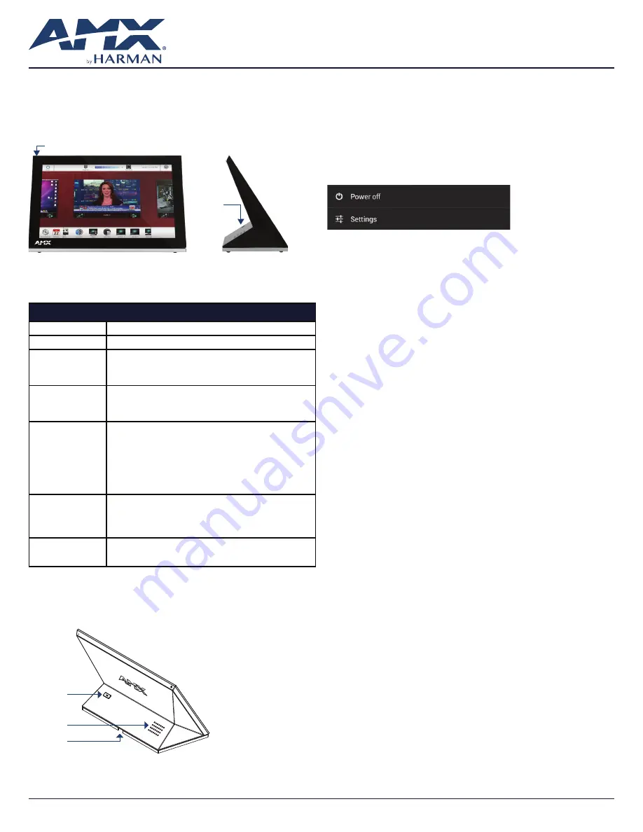
Sleep button
USB Port
(side view)
FIG. 1
MT-1002
Product Specifications
MT-1002 SPECIFICATIONS
Dimensions (HWD)
6 3/16” x 10 1/16” x 4 1/16” (157mm x 255mm x 103mm)
Weight
2.6 lbs (1.179 Kg)
Power
Consumption
• Full-On: 14.5 W maximum
• Standby: 5.8 W
• Shutdown: 1 W
• Start-Up Inrush Current: Not applicable due to PoE standard
External Power
Supply Required
Optimal performance requires use of one of the following AMX PoE
power supplies (not included):
• PS-POE-AT-TC, PoE Injector, 802.3AT Compliant (FG423-84)
• NXA-ENET8-POE+, Gigabit PoE Ethernet Switch (FG2178-64)
Certifications
• FCC Part 15 Class B
• CE EN 55032, 55035, 60950-1
• IEC 60950-1
• AS/NZS CISPR 32 Class B
• IC CISPR 22 Class B
• UL 60950-1
• VCCI CISPR 22 Class B
• RoHS
• WEEE
Environmental
• Temperature (Operating): 32°F to 104°F (0°C to 40°C)
• Temperature (Storage): 4°F to 140°F (-20°C to 60°C)
• Humidity (Operating): 20% to 85% RH
• Humidity (Storage): 5% to 85% RH
• Power (“Heat”) Dissipation: On: 49.5 BTU/hr, Standby: 19.8 BTU/hr
Included
Accessories
• MXA-USB-C, USB Port Cover Kit (60-5968-29)
• Cat5e Ethernet Cable, Flat Black (ECA2265-10)
• UTP CAT.5E Snap In Coupler, Black (64-5968-01)
Connector Locations
USB peripherals (mouse, keyboard, etc.) may be connected to the USB port on
the rear of the device. Updates to the device’s firmware can also made via the
USB port.
USB Port
Speaker
RJ-45 Port
FIG. 2
MT-1002 (REAR VIEW)
Power via Power Over Ethernet
Power for the MT-1002 is supplied via Power Over Ethernet (PoE), utilizing an
AMX-certified, capacitive touch-compliant PoE injector such as the PS-POE-
AT-TC, PoE Injector, 802.3AT Compliant (
FG423-84) or other approved AMX PoE
power source. The incoming Ethernet cable should be connected to the RJ45
port on the panel.
Powering On/Off Modero G5 Panels
Modero G5 touch panels may be powered on by touching and holding the
Sleep button. To power off the panel, press and hold the Sleep button, and
select
Power Off on the on-screen menu (FIG. 3):
FIG. 3
SLEEP BUTTON - PRESS AND HOLD TO ACCESS POWER OFF/SETTINGS OPTIONS
Configuration and Programming
Modero G5 touch panels are equipped with a
Settings menu that provides the
ability to configure various features on the panels. To access the
Settings menu,
press and hold the Sleep button, and select
Settings.
Note: Information on the Settings menu, panel configuration, and programming
is provided in the Modero G5 Programming Guide, available at www.amx.com.
Setting the Panel’s Device Number and Device Name
1. In the Settings menu, select
NetLinx. This opens a password keypad.
2. Enter the panel password into the keypad (the default is
1988) and select
OK to access the NetLinx page.
3. Press
Device Number to open the NetLinx editing window.
4. Enter a unique Device Number assignment for the panel and press
OK.
5. Enter a unique Device Name assignment for the panel and press
OK.
Configuring the Panel’s IP Address
The first step is to configure the panel’s IP address. Note that this only configures
the panel to communicate with a network; it is still necessary to connect to the
NetLinx Master (
see Connecting to a NetLinx Master below).
Network Communication via DHCP
1. In the
Ethernet page, press DHCP/Static field to open the DHCP/Static
window. Note that
DHCP is the default setting.
2. Select
Host Name, enter the new host name
3. Press
OK to save changes.
Network Communication via Static Address
1. In the
Ethernet page, press DHCP/Static to open the DHCP/Static window.
2. Select
Static to open the Static IP window.
3. Press any field to open a keypad or keyboard (depending on the field), and
enter the appropriate network address information.
4. Press
OK to save your changes and return to the Ethernet page.


