TECOM TS1001, Installation Manual
The PowerTec TS1001 Owner's Manual is a comprehensive guide for operating and maintaining your PowerTec TS1001 model. You can conveniently download this manual for free from our website, providing you with all the necessary instructions and information to fully utilize the features of your product.
Share
Download


Reviews:
No comments
Related manuals for TS1001

LEAD-PND-2150 Series
Brand: Portwell Pages: 27

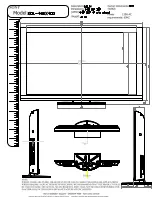
KDL-46HX800 - 46" Bravia Hx800 Led Backlit Lcd Hdtv
Brand: Sony Pages: 2

KDL-46HX800 - 46" Bravia Hx800 Led Backlit Lcd Hdtv
Brand: Sony Pages: 3

KDL-46EX710 - 46" Bravia Ex710 Series Led Hdtv
Brand: Sony Pages: 2

KDL-46HX701 - 46" Bravia Hx701 Series Hdtv
Brand: Sony Pages: 2

KDL-46EX600 - 46" Bravia Ex Series Hdtv
Brand: Sony Pages: 2

KDL-46EX700 - Bravia Ex Series Lcd Television
Brand: Sony Pages: 2

KDL-46EX700 - Bravia Ex Series Lcd Television
Brand: Sony Pages: 3

KDL-46EX600 - 46" Bravia Ex Series Hdtv
Brand: Sony Pages: 3

KDL-46EX400 - Bravia Ex Series Lcd Television
Brand: Sony Pages: 2

KDL-46EX500 - Bravia Ex Series Lcd Television
Brand: Sony Pages: 3

KDL-42XBR950 - 42" Flat Panel Lcd Wega™ Xbr Television
Brand: Sony Pages: 2
KDL-46EX400 - Bravia Ex Series Lcd Television
Brand: Sony Pages: 3

KDL-40WL140 - Bravia Lcd Television
Brand: Sony Pages: 2

KDL-40Z4100 - Bravia Z Series Lcd Television
Brand: Sony Pages: 2

KDL-40Z4100 - Bravia Z Series Lcd Television
Brand: Sony Pages: 64

KDL-40Z4100 - Bravia Z Series Lcd Television
Brand: Sony Pages: 111

KDL-40Z4100/S - Bravia Z Series Lcd Television
Brand: Sony Pages: 111


