Harman Stove Company P68, Owner'S Manual
The highly efficient Harman Stove Company P68 is a top-of-the-line pellet stove designed to bring warmth and comfort to your home. With its advanced features and easy operation, this stove guarantees optimal heating experience. Enhance your user experience with the free "Installation & Operating Manual" available for download from our website.
Share
Download


Reviews:
No comments
Related manuals for P68
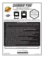
4300 Series
Brand: Quadra-Fire Pages: 32

Adele
Brand: evacalor Pages: 17

GF 160 DV
Brand: Jøtul Pages: 40

Vittoria V
Brand: Ravelli Pages: 36

SK 94
Brand: Olimpia splendid Pages: 8

VIVA 120
Brand: RAIS Pages: 339

S81-90
Brand: Morso Pages: 24

800180
Brand: EdilKamin Pages: 170

6910105
Brand: Clarke Pages: 28

Curvation:Siesta
Brand: Capital fireplaces Pages: 30

HSP 4.0-F1
Brand: HAAS + SOHN Pages: 36

44 Magnum
Brand: Harman Stove Company Pages: 25

1003063392
Brand: HAMPTON BAY Pages: 36

MILAN 76
Brand: Drija Pages: 18

Toscana 60
Brand: Drija Pages: 18

Milan 90
Brand: Drija Pages: 18

ET 3032
Brand: ECG Pages: 76

IKI UP
Brand: Palazzetti Pages: 8


