


Specifications, Applications,
Service Instructions & Parts
REFRIGERANT
FLOAT SWITCHES
Bulletin HLLe
SEPT 2013
for Ammonia, R22, R134a, CO
2
and Other Approved Liquids
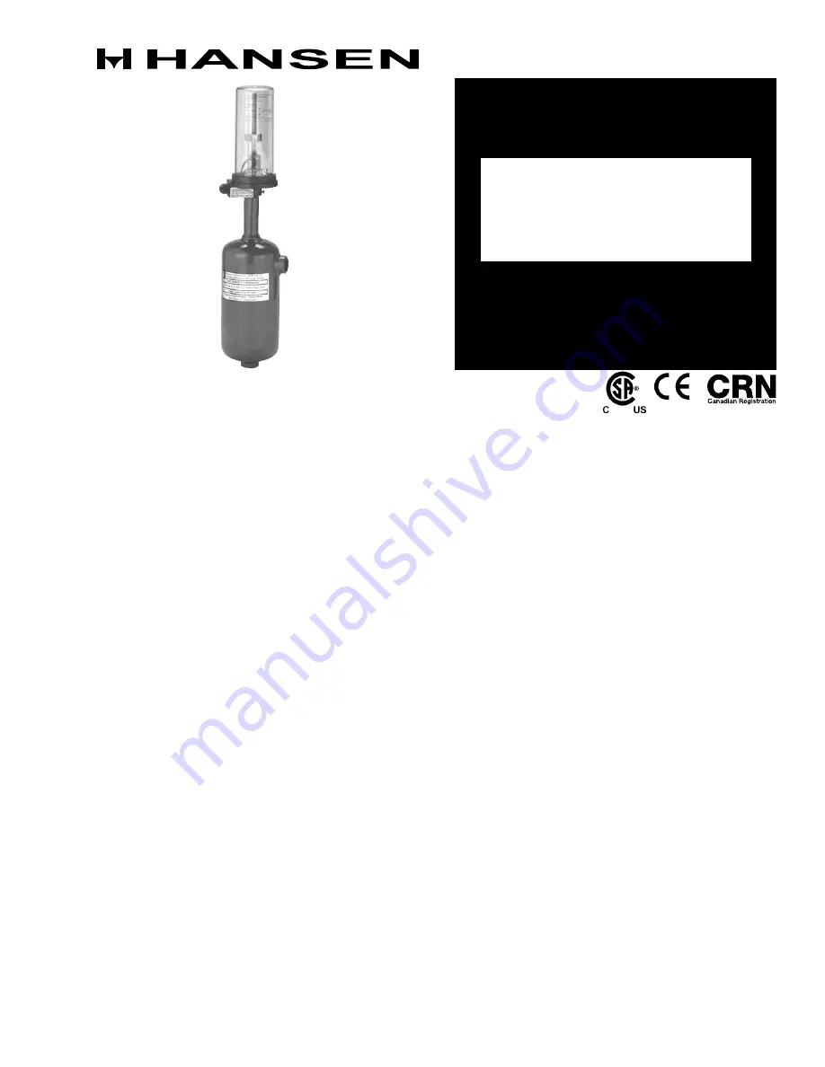
HLL Refrigerant Float Switch
INTRODUCTION
These Hansen refrigerant liquid level float switches
(HLL Series) are used to electrically indicate or control
a liquid level by opening or closing a SPDT switch. Their
simple, reliable design provides long life performance
for almost any application.
APPLICATIONS
These refrigerant liquid level float switches are typically
installed on a vessel’s liquid level column. They can
control liquid level by controlling a liquid fill solenoid
valve. Often, they are used to provide high level cut-
out or alarm. In addition, they can be used to turn off
a recirculating liquid pump if a low level occurs. Other
applications include control of liquid level via a liquid
exit solenoid valve, level indication via a pilot light,
and transfer drum operation.
MATeRIAL SPeCIFICATIONS
Safe Working Pressure: 400 psig (27 bar),
600 psig (40 bar) for CO2
Operating Temperature: -50ºF to +150ºF
(-45°C to +65°C)
Connections: ¾" FPT / 1" Butt Weld combination
Specific Gravity: 0.57 to 1.70
Electrical Switch: 120V, 240V, 10 amp SPDT
Connection: ½" NPSM for conduit, optional
DIN plug (3 wire plus ground)
ADVANTAGeS
Innovative features make these float switches the
superior selection. To overcome the most common
reason for existing float switch failure, switch burnout,
a heavy duty 10 amp snap action Honeywell SPDT
Micro Switch
®
is used. This switch is sealed in a
clear housing to allow visual confirmation of switch
action but protection from tampering. In addition, the
switch is surrounded by an inert gas which provides
an environment which inhibits corrosion. For ease of
installation, switch assembly position rotates 360°. If
the switch assembly should ever need to be replaced,
simply loosen the retaining screw and lift the lfoat
switch assembly off the top of the tank assembly.
Optional switch housing heater prevents moisture
penetration in humid environments.
Tank assembly is rugged, steel bodied with unique
combination ¾" FPT / 1" Butt Weld connections. Inside,
a high pressure tested float ball moves up and down via
a large diameter stem, overcoming potential bending
or breakage. Its movement is accurately guided by the
attractor and an alignment guide. Therefore, the float
ball assembly is not subject to the common, adverse
effects of normal oil and sludge build-up on the tank
interior walls. A deflector plate across the inlet of
the tank assembly protects the float ball against
sudden surges and provides smoother operation. In
addition, lower and upper cushioning springs provide
improved protection for the float ball. A standard 2"
(50 mm) differential prevents most short cycling due to
momentary changes in liquid level; other differentials
down to 0.5" (13 mm) are available. Because the tank
assembly is welded, it eliminates gasket leak potential
as well as tampering.


