


Specifications
Wingspan: 80-1/8"
Wing Area: 850 sq. in.
Weight (Approx.): 6.5-7.0 lbs.
Recommended Engines:
.40-.46 2-Cycle
.45-.60 4-Cycle
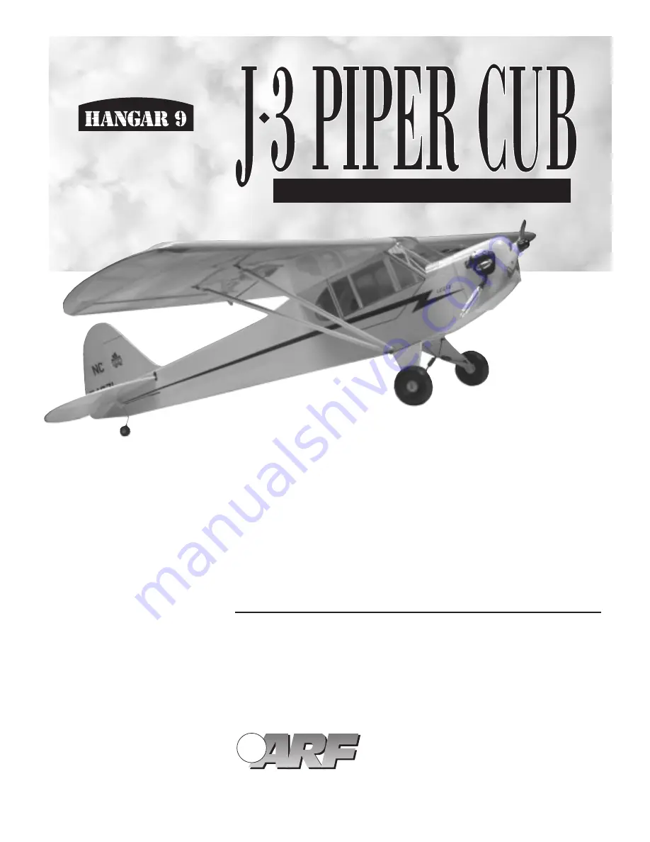
WE GET PEOPLE FLYING
TM
TM
Raising the Standard of Quality in
Almost Ready-To-Fly Aircraft
• Ultra Covering
• Pre-finished Fiberglass Cowl
• Highest Quality Craftsmanship
• 90% Pre-Built
• IMAA-Legal 80-1/8
"
Wingspan
ALMOST READY-TO-FLY
PRE-BUILT
90
%
ASSEMBLY MANUAL
Summary of Contents for J-3 Piper Cub
Page 44: ...HAN1501 ...


