AVSS PRS-M300, User Manual
The AVSS PRS-M300 is a high-quality audio system that provides exceptional sound clarity and immersive music experience. To make the most of this cutting-edge technology, don't forget to download the free User Manual from our website. It contains detailed instructions and troubleshooting tips to ensure a seamless user experience.
Share
Download


Reviews:
No comments
Related manuals for PRS-M300
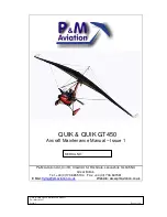
QUIK
Brand: P&M Aviation Pages: 54

Rans S-7 Courier
Brand: Fancy Foam Models Pages: 6

EC-130
Brand: Roban Pages: 48

Cessna F172 N
Brand: Reims Aviation Pages: 130

Garuda
Brand: Independence Pages: 17

Prymus 2
Brand: SOL paragliders Pages: 29

EXOCEAT
Brand: Ozone Pages: 14

61141
Brand: iKarus Pages: 73

LACY 2 HF
Brand: WAY Gliders Pages: 25

JS-MD 1C 2017
Brand: M+D Pages: 145

ARCUS M
Brand: Schempp-Hirth Flugzeugbau Pages: 173

HUGHES H-1
Brand: Maxford USA Pages: 13

C-5M
Brand: Lockheed Pages: 100

FES-LAK-P10-100
Brand: LZ design Pages: 9

FES FES-DIS-P1-102
Brand: LZ design Pages: 10

AS 13
Brand: LZ design Pages: 26

Airglider Power-Prop
Brand: In Vento Pages: 4

117350
Brand: In Vento Pages: 4


