background image

ASSEMBLY MANUAL

Specifications

Wingspan:  ............. 78.25 in (198.8 cm)
Length:  ................... 71.25 in (181 cm)
Wing Area:  ............ 1134 sq in (73.1 sq dm)
Weight:  .................. 12–15.5 lb (5.44–7.0 kg)
Radio:  ..................... 4-channel w/6 servos
Recommended Engines:  
    2-Stroke ............1.20–2.10
    4-Stroke ............1.50–2.20
    Gas .....................35–50cc
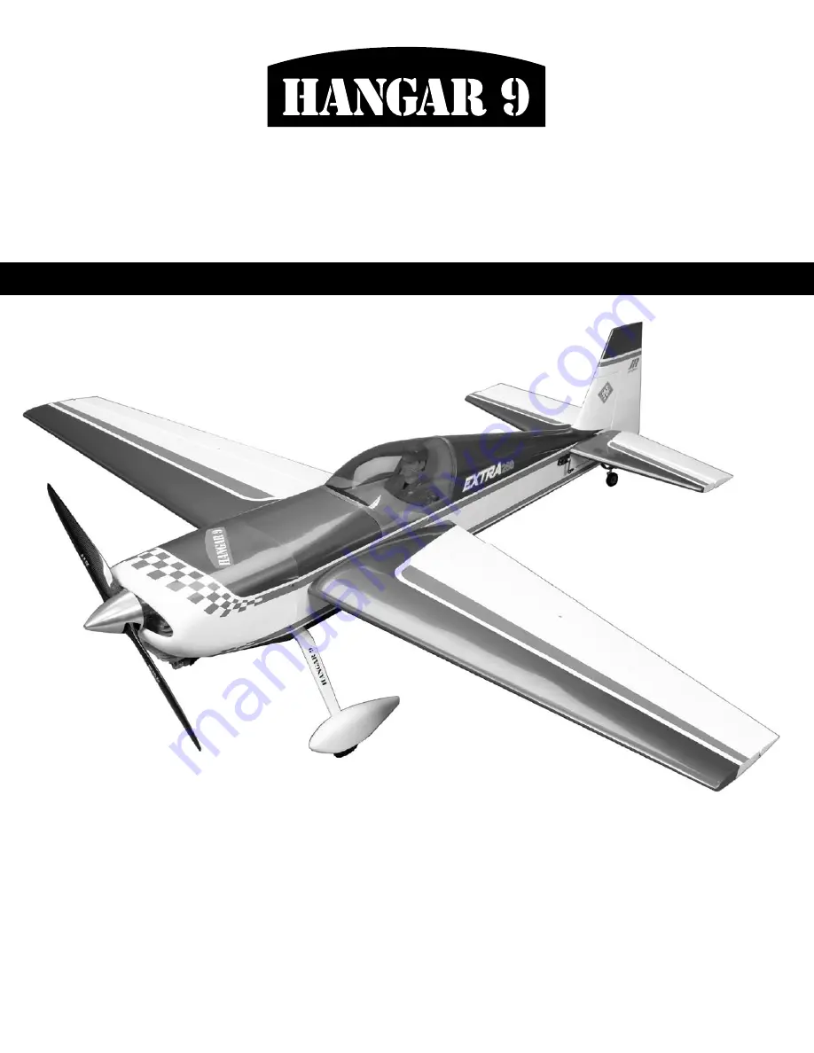
Extra 260

��

• Awsome IMAC and 3D performer
• Lightweight construction
• Designed by aerobatic veteran Mike McConville
• 90% factory built ARF
• Plug-in wings and stabilizers for easy transport and field assembly

Summary of Contents for Extra 260

Page 1: ...t 12 15 5 lb 5 44 7 0 kg Radio 4 channel w 6 servos Recommended Engines 2 Stroke 1 20 2 10 4 Stroke 1 50 2 20 Gas 35 50cc Extra 260 Awsome IMAC and 3D performer Lightweight construction Designed by aerobatic veteran Mike McConville 90 factory built ARF Plug in wings and stabilizers for easy transport and field assembly ...

Page 2: ...ator Servo Installation 15 Section 6 Landing Gear Installation 17 Section 7A Engine Installation Saito 19 Section 7B Engine Installation DA 50 22 Section 8A Rudder Servo Installation Saito 26 Section 8B Rudder Servo Installation DA 50 29 Section 9 Tail Wheel Installation 31 Section 10 Fuel Tank Installation 32 Section 11 Radio Installation 36 Section 12 Cowling Installation 37 Section 13 Hatch Ass...

Page 3: ...andard servo for throttle JRPS537 recommended or equivalent 4 hi torque servos JRPS8231 recommended or equivalent 1 hi torque servo JRPS8411 recommended or equivalent Recommended JR Systems PCM10X XP9303 XP6102 Recommended Engines Saito 1 50 2 20 Desert Aircraft DA 50 JR XP9303 JR PCM 10X Propeller Saito 1 80 APC 17x6 Saito 2 20 APC 18x8 DA 50 Mejelik 23x8 Spinner 31 4 12 Servo Extension JRPA098 2...

Page 4: ...ewdriver w short handle Foam 1 4 Hex wrench 3 32 Hobby knife Masking tape Phillips screwdriver small Razor saw Scissors Square Syringe Tap handle Toothpicks Velcro straps Adhesives 30 minute epoxy Medium CA cyanoacrylate glue CA remover debonder Pacer Z 42 Threadlock Pacer hinge glue PT 55 Formula 560 canopy glue Shoo Goo Other Required Items Epoxy brushes Felt tipped pen or pencil Measuring devic...

Page 5: ...he act of using the product the user accepts all resulting liability Once assembly of the model has been started you must contact Horizon Hobby Inc directly regarding any warranty question that you have Please do not contact your local hobby shop regarding warranty issues even if that is where you purchased it This will enable Horizon to better answer your questions and service you in the event th...

Page 6: ...lue syringe or toothpick place a sufficient amount of 30 minute epoxy into one of the hinge pockets in the aileron leading edge only Install one of the hinge points until the hinge pin center is flush with the leading edge of the aileron Some epoxy should ooze out of the pocket as the hinge is installed If not remove the hinge and apply more epoxy After gluing a few hinges you ll get the hang of j...

Page 7: ...s in one wing panel Step 5 Carefully attach the aileron to the wing making sure the hinges are inserted in their respective hinge pockets Press the aileron and wing together such that less than a 1 64 hinge line gap exists between the aileron and wing The bevels should virtually touch Use a paper towel and rubbing alcohol to wipe away any visible epoxy around the hinges Step 6 Double check the hin...

Page 8: ...d into the stabilizer towards the root Step 10 Repeat Steps 1 through 9 for the remaining aileron and elevator Hint Combining the left and right wing aileron and or left and right stabilizer elevator while waiting for glue to cure will make this section move along much quicker Step 11 Since all that s left is the rudder this is a good time to glue it as well Follow Steps 1 through 7 to complete hi...

Page 9: ...y 1 x 32 Fold the UltraCote down the center with the adhesive side to the outside making a sharp crease at the fold Step 2 Remove the backing from the UltraCote Place the folded crease side into the center of the hinge line on the bottom of the wing Using a straight edge as shown hold one side of the covering in place while ironing down the opposite side with a sealing iron We recommend setting th...

Page 10: ...tep 1 Install the servo hardware grommets and eyelets included with the servo Step 2 Plug a 12 servo extension onto the servo Either tie the servo leads together using a commercially available connector or use unwaxed dental floss to secure the extensions to prevent them from coming loose during flight Step 3 Tie a weight to a piece of string A wheel collar works great in this application Lower th...

Page 11: ...e servos Step 5 Mix a small amount of 30 minute epoxy and lightly coat the inside of the hole in the aileron and the 8 32 x 21 4 control horn screw Thread the screw into the hole from the top of the surface Wipe away any excess epoxy on the wing and screw with rubbing alcohol and a paper towel Screw the 8 32 flange nut in place as shown Allow the epoxy to fully cure Step 6 Screw the molded swivel ...

Page 12: ...tep 8 Screw a 4 40 ball link 5 to 6 turns onto each end of a 31 2 long aileron linkage Adjust the linkage length until the hole in the ball link aligns with the outer hole in the servo arm when the aileron is neutral and the servo arm is centered Step 9 Center the servo using the radio system Attach the servo horn to the servo using the screw provided with the servo Step 10 Attach the linkage to t...

Page 13: ...e fuselage Be sure the alignment pins are secure in the wing halves before installing the wings If they are not remove the pin and apply a small amount of thin CA into the tube socket and reinstall the alignment pin Step 3 Carefully slide the remaining wing panel onto the wing tube that projects from the fuselage The fit may be tight use caution when inserting the wing panels onto the wing tube an...

Page 14: ...ure the tube in the stabilizer Step 8 Slide the assembly into the fuselage Slide the remaining stab half onto the tube and drill and tap the location for the 4 40 retaining bolt Install the bolt to complete the procedure Hint When removing the stabilizer for storage remove only one bolt leaving the tube secured in the remaining stabilizer Trying to install the tube without the aid of an alignment ...

Page 15: ...sing servos with less torque could cause a crash Step 1 Install an 18 servo extension onto an elevator servo Either tie the servo leads together using a commercially available connector or use unwaxed dental floss to secure the extensions to prevent them from coming loose during flight Install one side only of the two Y harnesses to two of the servos also tying knots to prevent disconnection The o...

Page 16: ...s onto a 51 2 elevator linkage Screw the opposite end of the linkage into the swivel control horn on the elevator Adjust the linkage length until the hole in the ball link lines up with the outer hole in the servo arm when the elevator is neutral and the servo arm is centered Step 8 Use the included 4 40 screws and nuts to attach the ball link to the outer hole in the arm From the topside the corr...

Page 17: ...g an adjustable wrench and the nuts provided with the axles Step 2 Install the landing gear using four 8 32 x 3 4 socket head bolts four 8 washers and four 8 32 nylon lock nuts The lock nuts are placed inside the fuselage Step 3 Fit the pants over the axle on the landing gear Align the centerline of the wheel pant to the centerline of the fuselage Use a felt tipped pen to transfer the location of ...

Page 18: ...essary to fit the parts inside the wheel pant and slide them onto the axle Step 7 Secure the pant in place using a 4 40 x 1 2 socket head screw and 4 washer Use threadlock on the screw to prevent it from coming loose in flight Step 8 Center the wheel in the wheel pant and tighten the collars to prevent the wheel from moving side to side Use threadlock on both set screws Step 9 Repeat Steps 3 throu...

Page 19: ...ition an engine mount onto the narrow edge of a block Mark the locations for the mounting bolts onto the block Step 2 Use a 3 16 drill and drill press to drill the two holes through the blocks Step 3 Temporarily attach the engine to the engine mount using four 8 32 x 1 screws four 8 32 locknuts and four 8 washers Position the arrows on the mounts so they face towards the head of the engine Step 4 ...

Page 20: ...the mount halves as shown These will be the same no matter what engine if you are using the supplied mount Note The engine is not centered between the engine mount holes The lines drawn for the mount reflect this Step 7 Take the measurement from Step 5 and divide it by two For the Saito this will be 13 16 Use this measurement to mark the positions above and below the centerline for the engine moun...

Page 21: ...ation for the throttle pushrod Mark the location with a felt tipped pen Remove the engine and drill the firewall for the pushrod tube using a drill and 5 32 drill bit Step 12 Roughen the tube using medium sandpaper Slide the tube into position and use medium CA to glue it to the firewall Step 13 Trim the tube 1 2 in front of the throttle servo tray Place a 1 4 piece of fuel tubing onto a clevis th...

Page 22: ... using the instructions provided with the engine Also collect all the items required for the exhaust system at this time Step 2 Mark the centerline for the engine onto the firewall Note the vertical centerline is offset to the right side of center as viewed from the front due to the built in right thrust These will be necessary no matter what engine you choose to install Step 3 Measure the distanc...

Page 23: ...anister style muffler Step 5 Mark the former as shown The area below and between the engine box will be removed Use a hobby knife rotary tool and saw to remove the area from the sub firewall Step 6 Remove the covering 1 2 away from the sides of the fuselage Use a covering iron to iron the excess material down into the fuselage Remember to seal the wood inside the fuselage to protect it from fuel a...

Page 24: ...muffler Fit the muffler into the opening made in the former and adjust as necessary to provide adequate clearance around the muffler Step 8 Position the exhaust stinger directly down so the exhaust exits the aircraft Bolt the exhaust header to the engine Section 7B Engine Installation DA 50 ...

Page 25: ...Mark the location with a felt tipped pen Remove the engine and drill the firewall for the pushrod tube using a drill and 5 32 drill bit Step 12 Roughen the tube using medium sandpaper Slide the tube into position and use medium CA to glue it to the firewall Step 13 Trim the tube 1 2 in front of the throttle servo tray Place a 1 4 piece of fuel tubing onto a clevis then thread the clevis onto the 1...

Page 26: ...os with excellent results Using servos with less torque could result in blow back Step 1 Thread the 8 32 x 4 control horn screw into the hole in the rudder and epoxy in place Thread the 8 32 flange nuts onto the screw from both sides of the rudder Position the screw so it is centered in the rudder Use threadlock on the nuts to prevent them from loosening during flight Step 2 Cut the cable into two...

Page 27: ...cable into the fuselage through the opening Step 5 Using the screws included with the servos fasten the servos in place You may find it helpful to drill a 1 16 pilot hole before installing the screws Step 6 Prepare the rudder servo arm by attaching two 4 40 ball links using the standoffs and 4 40 lock nuts Step 7 Center the rudder servo and place the servo arm onto the servo Slide a crimp onto the...

Page 28: ... Repeat Steps 2 through 8 to assemble and install the second rudder cable Step 5 is only required once Step 10 With the radio on check the operation of the rudder Adjust the cables so when the rudder servo is centered the rudder is centered as well There will be tension on the cables Adjustments can be made at the rudder control horn and at the servo arm Once adjustments are made secure the servo ...

Page 29: ...ly available connector or use unwaxed dental floss to secure the extension to prevent it from coming loose during flight Step 2 Remove the covering from the fuselage for the rudder servo location Install the servo in the fuselage tail section with the output shaft to the rear as shown in the photo Step 3 Using the screws included with the servos fasten the servos in place You may find it helpful t...

Page 30: ...ep 7 Use the included 4 40 screws and nuts to attach the ball link to the outer hole in the arm The correct sequence is 4 40 screw ball link servo arm and 4 40 locknut Be sure to use threadlock Step 8 Screw a 4 40 ball link 5 to 6 turns onto the 5 rudder linkage Screw the opposite end of the linkage into the swivel control horn on the rudder Adjust the linkage length until the hole in the ball lin...

Page 31: ...elage Using a felt tipped pen mark the positions for the mounting screws through the tail wheel bracket Step 3 Remove the bracket and drill 5 64 pilot holes at the previously marked positions Step 4 Use two 4 x 5 8 sheet metal screws to secure the tail wheel bracket in place A hardwood plate is positioned in the rear of the fuselage allowing these screws to be firmly tightened Hint Remove the scre...

Page 32: ...engines While the stopper is OK for both gas and glow the fuel tubing supplied is for glow engines only If a gasoline engine is used use Tygon tubing not included for all lines inside and outside the fuel tank Step 1 Locate the fuel tank parts Step 2 Locate the rubber stopper Insert the shorter metal fuel tube into one of the holes in the stopper so that an equal amount of tube extends from each s...

Page 33: ...silicone tubing Slide the silicone tubing end opposite the clunk onto the fuel tank pickup tube straight tube in the stopper Step 7 Carefully insert the stopper assembly into the fuel tank Note the position of the vent tube it must be up at the top portion of the fuel tank to function properly Also it may be necessary to shorten the length of the fuel pickup tubing to make sure the clunk does not ...

Page 34: ...m In turn you will not get the optimum performance from your engine Step 9 Connect two 12 pieces of fuel tubing for pickup and vent tubes Attach the green tubing to the pick up the red to the vent Step 10 Cut a piece of 1 4 foam and attach it to the bottom of the fuel tank Install the fuel tank into the fuselage Use the 15 tie wrap to secure the tank into position in the fuselage Step 11 Make the ...

Page 35: ...f Tygon tube onto the vent to extend it to the top of the tank Fuel Tubing When using gas engines Tygon fuel tubing must be used The supplied tubing is for glow enine use only Stopper Assembly When preparing the stopper assembly apply a drop of solder to the ends of the brass tubing where the fuel lines attach Securing the Fuel Tubing Wire ties must be used to secure the fuel lines to the tubing I...

Page 36: ...sing a DA 50 and canister exhaust epoxy the two hardwood standoffs under the servo to raise it away from the canister The servo mounts directly onto the standoffs Step 4 Move the servo to the throttle open position using the radio system Manually move the throttle arm on the carburetor to the open position Mark the pushrod where it crosses the servo arm Make a 90 degree bend in the wire and instal...

Page 37: ...2 Attach the cowling onto the fuselage using four 4 40 x 1 socket head screws four 4 washers and four pieces of 1 4 long fuel tubing Transfer the positions from the cardstock onto the cowling Step 3 Remove the cowl from the fuselage Use a rotary tool and sanding drum to remove material to allow access to items such as needle valves glow plugs cut off switches mufflers etc Note Start by removing on...

Page 38: ...e of the cowl for an air exhaust This is important for engine cooling For DA 50 and canister muffler For DA 50 and pitts muffler Step 5 Install the propeller and spinner to complete the cowling installation Section 12 Cowling Installation ...

Page 39: ...ible Let the glue dry before securing the canopy in place Step 3 Position the canopy onto the canopy hatch Trace around the canopy and onto the hatch using a felt tipped pen Step 4 Lightly sand the inside edge of the canopy and slightly inside the line drawn on the hatch using medium sandpaper Step 5 Apply a bead of RCZ56 Canopy Glue ZINJ5007 around the inside edge of the canopy Position the canop...

Page 40: ...tor coupling Rudder to aileron mixing to correct rudder to aileron coupling When using a 6 channel or greater computer radio each servo is plugged into its own separate channel Consult your radio manual for specific details on hookup and programming If using a 6 channel radio with flaperon mix the aileron servos are each plugged into their own channels The right aileron plugs into the aileron sock...

Page 41: ...the range first with the engine not running and note the distance Next start the engine With the model securely anchored check the range again The range test should not be significantly effected If it is don t attempt to fly Have your radio equipment checked out by the manufacturer Step 2 Double check that all controls aileron elevator rudder and throttle move in the correct direction Step 3 Be su...

Page 42: ...sion are limited to a maximum weight of 3 3 pounds and a G series motor A model aircraft is defined as an aircraft with or without engine not able to carry a human being 8 I will not consume alcoholic beverages prior to nor during participation in any model operations 9 Children under 6 years old are only allowed on the flight line as a pilot or while receiving flight instruction RADIO CONTROL 1 I...

Page 43: ...stants callers and officials are on the course 1 All officials callers and contestants must properly wear helmets which are OSHA DOT ANSI SNELL or NOCSAE approved or comparable standard while on the racecourse 2 All officials will be off the course except for the starter and their assistant 3 On the course is defined to mean any area beyond the pilot staging area where actual flying takes place B ...

Page 44: ... 2005 Horizon Hobby Inc 4105 Fieldstone Road Champaign Illinois 61822 877 504 0233 www horizonhobby com 7422 ...

Reviews: