background image


SERVICE MENUAL 


FOR LCD TV 15”/17”/20” 


TFT-LCD TV/MONITOR


Haier Group 

Summary of Contents for L15SV6-A0

Page 1: ...SERVICE MENUAL FOR LCD TV 15 17 20 TFT LCD TV MONITOR Haier Group ...

Page 2: ...S 2 Main Unit Description 3 Features 4 Warning and Cautions 5 Replacement of Memory IC 6 Net Dimension 7 Remote Controller Functions 8 Principle ICS 9 Block Diagram 10 Exploded View 11 List of Parts 12 Trouble Shooting ...

Page 3: ... item Press to enter the submenu 4 PRO TV channel down to select the item in the menu 5 PRO TV channel up to select the item in the menu 6 TV AV Select the input signals PC RGB AV S VIDEO TV 7 Remote Sensor Receiving remote controller sends the infrared remotesignal 8 Power supply switch 9 Power indicator Illuminates red in standby mode illuminates green when the display is turned on ...

Page 4: ......

Page 5: ...PAL SECAM 9 NO of preset channels 100 100 100 10 Picture mode Yes Yes Yes 11 Angel of view 176o 176o 120o 12 Color display 16777216 16777216 16777216 13 Color level 16 16 16 14 OSD languages 8 8 8 15 AV stereo Yes Yes Yes 16 Surrounding sound No No No 17 Audio system DK BG I L L DK BG I L L DK BG I L L 18 Bass No No No 19 Balance Yes Yes Yes 20 Sound mode Yes Yes Yes 21 Mute Yes Yes Yes 22 NICAM Y...

Page 6: ...Quick View Yes Yes Yes 39 C NO NO NO 40 PIP NO NO NO 41 NO of built in speakers 2 2 2 42 NO of outer speakers NO NO NO 43 Audio output power Built in W 2 1 5 2 1 5 2 1 5 44 Audio output power outer W 2 1 5 2 1 5 2 1 5 45 Total power input W 60 60 60 46 Voltage range V 100 240 100 240 100 240 47 Power frequency Hz 50 60 50 60 50 60 48 Time of sleep timer MINS 240 240 240 49 Net weight KG 50 Gross w...

Page 7: ...azard Do not expose the main unit to rain or moisture Warning Do not drop or push objects into the television cabinet slots or openings Never spill any kind of liquid on the television receiver Minimum Caution If the television is to be built into a compartment or similarly enclosed the minimum distances must be maintained Heat build up can reduce the service life of your television and can also b...

Page 8: ... the AC outlet Caution Avoid exposing the main unit to direct sunlight and other source of the heat Do not stand the television receiver directly on other produces which give off heat E g video cassette players Audio amplifiers Do not block the ventilation holes in the back cover Ventilation is essential to prevent failure of electrical component Do not squash power supply cord under the main unit...

Page 9: ...with the initial data values or blank memory IC 3 Power On Plug the 12V power plug into 12V power socket If memory IC is blank the program will take 25s to initial memory IC 4 Check and set SYSTEM default value 1 Press DISPLAY key then press colour key red green yellow DISPLAY on the Remote control unit continuously for factory used 2 The Factory2 will be displayed on the screen 3 Check the settin...

Page 10: ...6 Net Dimension 1 L20AV6 A0 2 L17LV6 A1 ...

Page 11: ...3 L15SV6 A0 ...

Page 12: ... TV Illustration of the keys on the remote control 1 Power Power supply switch 2 M U TE M U TE 3 DISPLAY Display current input signal information 4 0 9 TV channel number select 5 SLEEP Set time to change the TV into the standby status after a period of preset time time is 240 180 120 90 60 45 30 15 0 ...

Page 13: ...e 15 ARC Is not available except L17L6A G1 L17LV6 A1 L17G1 A0 Press this key the present size will be on the screen Thenuse V to adjust the picture size between Fill all and 4 3 16 AUTO AD A u t o a djust PC mode 17 RED 18 CYAN 19 GREEN 20 YELLOW Correspond to the differently colored subjects 21 TEXT Switch to the Teletext with text mode turn off Teletext and switch to TV mode 22 HOLD Hold on or o...

Page 14: ...ding earth wire to prevent possibleelectric shock If grounding methods are not possible have a qualifiedelectrician install a separate circuit breaker Do not try to ground the unit by connecting it to telephone wires lightening rods or gas pipes ...

Page 15: ...8 Principle ICS 1 Uoc3 Function TV signal processor with Teletext and Nicam ...

Page 16: ......

Page 17: ......

Page 18: ...2 NT68521 Function Scaler ...

Page 19: ......

Page 20: ......

Page 21: ...3 SM5964 PLCC Function MCU ...

Page 22: ...4 TPA1517NE Function Audio power amplifier ...

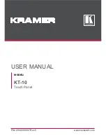
Page 23: ...9 Block Diagram ...

Page 24: ...10 Exploded View NUM PARTS NAME 1 Front Frame 2 LCD Screen 3 LCD Module Shield Borad 4 LCD Screen 5 Whole Engine 6 Loudhailer 7 NO 8 Rear Cover 9 Bracket 10 Key Board Bracket ...

Page 25: ...f screw 50 0094300481 Connecting wire for LCD 16 0090600015 Accuse self screw 51 0090402777 Connecting wire for Background light 17 0090600230 Accuse self screw 52 0094010332 Background lightdriving board 18 0090600011 Accuse self screw 53 0090205604 Control panel key 1 19 0090600012 Accuse self screw 54 0090205605 Control panel key 2 20 0090600012 Accuse self screw 55 0090505908 Carton 21 0090402...

Page 26: ...te control 26 0090101071 Connecting board 53 0090600197 Screw 27 0090101072 Metal jack plank 54 0090203652 Screw package 3 L15SV6 A0 1 DC0MY0E0K00 L15SV6 A0 26 0090402784 LVDS wire 2 0094014592 Main board subassembly 27 0090402274 speaker wire 3 0094014594 Control subassembly 28 0094014419 inverter 4 0090808930 Front frame subassembly 29 0090402828 Connective wire for control 5 0094013877 LCD disp...

Page 27: ...12 Trouble Shooting 1 Power supply Trouble 2 Display trouble 2 1 Exceptional screen ...

Page 28: ...2 2 White screen 2 3 Black screen ...

Page 29: ...3 Audio Trouble 4 Function Touble 4 1 TV 1 ...

Page 30: ...4 1 TV 2 4 3 PC ...

Page 31: ...4 4 SCART RGB SCART Video S Video AV ...

Page 32: ...Sincere forever Tel 86 532 88938356 ...

Reviews: