Haas Automation Toolroom Mill, Addendum
The Haas Toolroom Mill Operator's Manual is essential for harnessing the full potential of your machine. Experience smooth operation, precision milling, and efficient results, all with this detailed manual. Download your free copy of the Haas Toolroom Mill Operator's Manual from our website manualshive.com, to maximize your productivity and machine performance.
Share
Download


Reviews:
No comments
Related manuals for Toolroom Mill
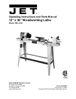
JWL-1236
Brand: Jet Pages: 20
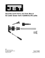
Elite E-1236VS
Brand: Jet Pages: 8
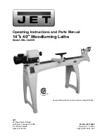
JWL-1440VS
Brand: Jet Pages: 32

C0
Brand: Axminster Pages: 13

1001
Brand: BURR KING Pages: 22

70-200EVS
Brand: Rikon Power Tools Pages: 16

DB 1100
Brand: Holzstar Pages: 22

G9249
Brand: Grizzly Pages: 92

DSBA-40
Brand: Wood-mizer Pages: 47

Pro LTPROCBN-110
Brand: Wood-mizer Pages: 60

TRL 1630HSRX
Brand: TRAK Pages: 122


