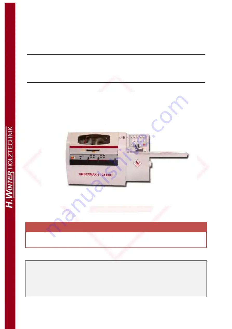
background image


OPERATION MANUAL  

FOUR SIDE MOULDER


WINTER TIMBERMAX 4 – 23 ECO


WARNING!


The operator must thoroughly read this manual before operation. 

Keep this manual for future reference.


Henrik Winter Holztechnik GmbH


Druckereistr. 8 

04159 Leipzig 


Tel: +49 (0)341/ 4619021 Fax: +49 (0)341/4618358 Funk: +49 (0)171/2820443 

Em@il: [email protected] Internet: www.winter-holztechnik.de 


Summary of Contents for TIMBERMAX 4-23 ECO

Page 1: ...must thoroughly read this manual before operation Keep this manual for future reference Henrik Winter Holztechnik GmbH Druckereistr 8 04159 Leipzig Tel 49 0 341 4619021 Fax 49 0 341 4618358 Funk 49 0...

Page 2: ...of machine tool 6 5 2 Main technical parameters 8 6 Overall size of machine tool 9 7 Portage and installation of machine tool 10 7 1 Portage of machine tool 10 7 1 1 Portage by forklift 10 7 2 Disposa...

Page 3: ...and backward adjustment of universal spindle 29 8 10 3 Elevation adjustment of universal spindle 29 8 10 4 Positive and negative selection of universal spindle 29 8 11 Adjustment of insert and fence 3...

Page 4: ...power 42 12 List of generally replaced standard parts 43 12 1 Bearings 43 12 2 Belt 44 13 Function introductions of control panel 44 13 1 Function introduction of main control panel 44 13 2 function...

Page 5: ...WINTER TIMBERMAX 4 23 ECO 7 1 Spindle Arrangement 1 1 Spindle Arrangement Example RMM523UE RMM423E bottom spindle top spindle right spindle left spindle universal...

Page 6: ...protected covers while processing neither adjust the wind tubes feeding wheels and side pressure wheels Do not clean the chips while the machine is running for fear that dangers might cause Do not tr...

Page 7: ...ties While observing and checking the equipments herein the equipment shall be stopped and cannot be started up the runner must ensure the selection switch is switched to test and others cannot change...

Page 8: ...e electricity 2 Safety protector Runners must wear protective goggles 3 Safety protector Runners must wear ear protector 4 Keep safe Caution machanical injury 5 Cutter blocks rotating watch out 6 Elec...

Page 9: ...orkpieces only limit to the data of technical parameters Do not use if the data overruns Do not process the timber with nail or concrete The cutter tools must be made in accordance with EN847 1 manufa...

Page 10: ...meter 8mm Dust collecting Wind speed must be 30 34 m s dust intakes of ID Inner Diameter 120mm wind cost m h please see the table below TABLE 2 4 spindle machine 5 spindle machine Wind Min 4900 6110 M...

Page 11: ...eumatic control area Workpiece guiding 4 Infeed table 5 Infeed fence 6 Side pressure wheel components of left spindle 7 Guiding fence 8 Side pressure board 9 feeding pressure wheel Spindle 10 bottom s...

Page 12: ...ax 140 Thickness of pre trimming cutter mm 10 Axial adjustable range of spindles mm 20 Motor power kW HP 4 5 5 5 5 7 5 7 Vertical milling cutter spindle speed r min 6000 Diameter of spindle mm 40 OD o...

Page 13: ...WINTER TIMBERMAX 4 23 ECO 9 6 Overall size of machine tool Figure 2 TABLE 4 G23 4E G23 5E L 3425 4260 W 1485 1489 H 1517 1517 A 1579 2414 B 1579 2414 model size...

Page 14: ...er the empty place of machine tool and raise the machine tool carefully Please see Figure 3 Figure 3 Attention Extend the arms of forklift slowly under the empty place guiding groove for forklift of m...

Page 15: ...WINTER TIMBERMAX 4 23 ECO 11 7 2 Disposal of machine tool Figure 4 Note The size of L W H please see Table 4...

Page 16: ...lt This machine does not need the base bolts for installation and fixing generally If it is demanded installation dimension of base bolts please see Figure five six RMM423E A A 1026 366 40 104 0 1352...

Page 17: ...machine tool Place pad 2 under the adjusting bolt 1 of the base Place a level gauge 3 on the machine table perfect to be the center of the machine Adjust the level of machine via the adjusting screw...

Page 18: ...Bottom spindle No Right spindle No Left spindle 1 Radial locking bar 5 Radial adjusting bar 8 Radial adjusting bar 2 Radial adjusting bar 6 Axial adjusting bar 9 Axial adjusting bar 3 Axial adjusting...

Page 19: ...locking motion rotate the locking bar clockwise to lock the orientation 4 Axial motion of right spindle Rotate the adjusting bar clockwise and the spindle moves upwards Rotate the adjusting bar anti c...

Page 20: ...clockwise and the spindle moves backwards 11 Radial motion of top spindle Rotate the adjusting bar clockwise and the spindle moves upwards Rotate the adjusting bar anti clockwise and the spindle move...

Page 21: ...ction of symbols 15 U Rotate angle adjustment of universal spindle Rotate the adjusting bar clockwise and the spindle leans forwards Rotate the adjusting bar anti clockwise and the spindle leans backw...

Page 22: ...nch 7 to lock the locknut 5 on the spindle Attention a The blades should be in a same cutting circle while installing the blades Especially ensure that the nips of blades must be firmly installed and...

Page 23: ...justed by radial and axial directions The adjustable quantity can be displayed by digital indicator Steps of adjustment Loosen the locking bar Adjust the radial or axial spindle position by rotating t...

Page 24: ...ps of adjustment see Figure11 Loosen the locknut 2 on the adjust ring 1 of digital indicator Rotate the adjust ring 1 to the value in need Attention The last rotate direction of digital indicator must...

Page 25: ...sting bar to adjust the height of infeed table 4 in need The adjustable range is 0 10mm screw adjusting bar 2 after finished then lock lokcnut 5 Figure12 8 5 2 Adjustment of feeding fence The forward...

Page 26: ...touches the inner surface of guiding board 4 the timber would be guided by guiding board 4 and no longer guided by feeding fence 1 Then this right angle will be milled by right vertical milling cutter...

Page 27: ...k The correct position adjusted is when the edge 4 touches the cutter adjusting ruler 6 d Lock the radial locking bar 8 Figure14 Axial adjustment of 1st bottom spindle The axial adjustment of 1st bott...

Page 28: ...djusting ruler 2 Set the value of digital indicator For example set the value into 62 5mm when the radius of cutter block is 62 5mm Figure15 8 7 2 Axial adjustment of right spindle The Axial adjustmen...

Page 29: ...clings to test piece 3 Set the value of digital indicator into L Figure17 8 8 2 Axial adjustment of left spindle The axial adjustment of left spindle please see Figure18 Put a spindle ring 1 of 10mm...

Page 30: ...the value of digital indicator into H Digital indicator please see No 2 in figure 27 Figure19 8 9 2 Axial adjustment of top spindle The axial adjustment of top spindle please see Figure20 Let a spind...

Page 31: ...ngle of 360 degrees of spindle The universal spindle can process every last part of the workpieces The preparative works needs before adjusting please see Figure21 Loosen bolt 1 and locking bar 4 move...

Page 32: ...is settled as a top or bottom spindle the motor shall be adjusted by the side of the operator as shown in Figure a Figure a When the universal spindle is settled as a left or right spindle the motor s...

Page 33: ...irection locking bar 2 8 10 3 Elevation adjustment of universal spindle The elevation adjustment of universal spindle please see Figure22 Loose bar 2 Rotate adjusting bar 3 accoring to symbols move up...

Page 34: ...ar pressure board 1 loosen bolt 3 adjusting screw 4 to make tangency of cutter s cutting blade and cutter adjusting ruler Set the value of readout 5 into 60 Lock bolt 3 Figure25 Press cutter adjusting...

Page 35: ...pressure part 2 0 5 1mm compressed quantity lower than cutter edge 3 Chip breaker 4 is of 3 5mm compressed quantity The pressure shoe must be adjusted to the center of the width of workpiece Looson b...

Page 36: ...sting bar then adjust by rotating the adjusting screw The readout 2 will show the position of the feed beam Figure27 Electric elevation of feed beam The electric elevation of feed beam please see 14 2...

Page 37: ...f lockbolt When feeding wheels 1 achieves the requirement the lockbolt surface will meet rocker Lock nut 2 after the adjustment is done Attention Before leaving factory the feeding wheels before top s...

Page 38: ...e password 6 Use to set or change the value of the parameter 7 Press OK to confirm the selection value of parameter 8 Use to select the next group of parameter 9 Exit the parameter setting press twice...

Page 39: ...pressure setting 0 1 0 2MPa 2nd section of feeding steel wheel pressure setting 0 2 0 3Mpa 3rd section of feeding rubber wheel pressure setting 0 3 0 4Mpa 3 2 1 pressure indicator pressure adjusting k...

Page 40: ...he insulated resistance of electric equipment before the first electrify This can only be done by qualified electrician According to the power on the brand and the attached technical requirement of el...

Page 41: ...ration can only be carried out by qualified electrician Press emergency stop SB1 on the main control panel wait 45 seconds till the safety indicator HL10 lights then to open the cover and operate Mach...

Page 42: ...es 80 Function inspection 10 2 2 Adjustment of spindle belts Loose and tight of spindle belt please see 8 21 The magnitude of loose and tight of transmission is controlled by the elongation of belt Le...

Page 43: ...ng cutter wears out seriously because of processing the raw wood block with same width frequently Re adjust the pressure wheel to the center of workpiece Re sharpen the planing cutter 4 The workpieces...

Page 44: ...wheel is not correct b The pressure of the side pressure part is not even a Adjust the feeding pressure wheel to the workpiece central b Check all pressure parts 10 Tracks of the feeding wheel appear...

Page 45: ...SS Stellite alloy steel Stellite Hard metal alloy steel Hardmetal 2 Cutter edge broken a Too high Temperature when re sharpen b Too big back angle a Select suitable grinding wheel when re sharpening t...

Page 46: ...not be operated a Emergency stop button has been pressed down b The cover is opened c The min breaker on the control transformer is overheated broken d Air switch of the motor is cut off e Supply of a...

Page 47: ...4 Vertical moving slide assembly of universal Thrust ball bearing 51104 Horizontal moving slide assembly of universal Deep slot ball bearing 6005 2RS Horizontal moving slide assembly of universal Deep...

Page 48: ...indle 13 Function introductions of control panel 13 1 Function introductions of main control panel Main control panel INVERTER STOP 0 RESET TIMER U 6 15 3 0 Rese t On Hand Off On Auto O n W a r n A l...

Page 49: ...s emergency button to restore you should press this button the machine will start up again when the light is on 3 0 Working light selection switch Turn to 1 the woking light will be on Turn to 0 worki...

Page 50: ...ou can open the cover and do any operation at this time 7 Feed beam elevation knob Clockwise rotate the knob for lifting anti clockwise for falling 8 Feeding start up button Press this button and feed...

Page 51: ...irection Turn the switch to and universal spindle rotates clockwise Turn the switch to and universal spindle rotates withershins 13 Universal spindle and feeding interlock selection switch Turn to the...

Page 52: ...le stops Press start or stop button to start or stop the left spindle 17 STOP START 1st top spindle starts 1st top spindle stops Press start or stop button to start or stop the 1st top spindle 18 STOP...

Page 53: ...on the control panel If not change random 2 of the 3 pieces of power supply cable This operation can only be carried out by qualified electrician Press emergency stop SB1 on the main control panel wai...

Page 54: ...verter please see content 8 15 1 14 7 Normal stop and emergency stop Normal stop Press stop feeding SB7 on the control panel to stop the feeding device then stop each spindle and the machine stops Eme...

Reviews: