background image

COPYRIGHT © MAY, 2020 BY GRIZZLY INDUSTRIAL, INC.


WARNING: NO PORTION OF THIS MANUAL MAY BE REPRODUCED IN ANY SHAPE

 OR FORM WITHOUT THE WRITTEN APPROVAL OF GRIZZLY INDUSTRIAL, INC.

#CS20952  PRINTED IN CHINA

V1.05.20

MODEL T32004

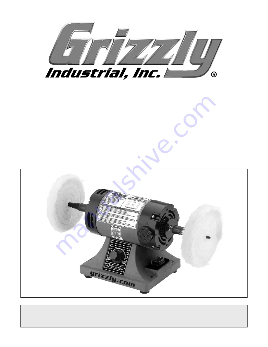
3/4 HP VARIABLE-SPEED

MINI BENCHTOP BUFFER

OWNER'S MANUAL

(For models manufactured since 02/20)

Summary of Contents for T32004

Page 1: ...PORTION OF THIS MANUAL MAY BE REPRODUCED IN ANY SHAPE OR FORM WITHOUT THE WRITTEN APPROVAL OF GRIZZLY INDUSTRIAL INC CS20952 PRINTED IN CHINA V1 05 20 MODEL T32004 3 4 HP VARIABLE SPEED MINI BENCHTOP BUFFER OWNER S MANUAL For models manufactured since 02 20 ...

Page 2: ...ng grinding tool integrity and the usage of personal protective equipment The manufacturer will not be held liable for injury or property damage from negligence improper training machine modifications or misuse Some dust created by power sanding sawing grinding drilling and other construction activities contains chemicals known to the State of California to cause cancer birth defects or other repr...

Page 3: ... Considerations 13 Bench Mounting 13 Assembly 14 Test Run 15 SECTION 4 OPERATIONS 16 Buffing 17 Installing Removing Buffing Wheel 18 Selecting Buffing Compounds 19 Loading Compound 19 SECTION 5 ACCESSORIES 20 SECTION 6 MAINTENANCE 22 Schedule 22 Cleaning 22 Lubrication 22 SECTION 7 SERVICE 23 Troubleshooting 23 Replacing Motor Brushes 24 SECTION 8 WIRING 25 Wiring Safety Instructions 25 Wiring Dia...

Page 4: ...made every effort to be exact with the instruc tions specifications drawings and photographs in this manual Sometimes we make mistakes but our policy of continuous improvement also means that sometimes the machine you receive is slightly different than shown in the manual If you find this to be the case and the difference between the manual and machine leaves you confused or unsure about something...

Page 5: ...d locations of the controls and features shown below to better understand the instructions in this manual Buffing Wheel Variable Speed Dial ON OFF Switch Spindle Sleeve Motor Brush Cap 1 of 2 Motor To reduce your risk of serious injury read this entire manual BEFORE using machine ...

Page 6: ...hen operating this machine A Buffing Wheel Spins to buff workpiece Can be replaced with different buffing pol ishing wheels for different operations and compounds B Spindle Sleeve Secures and spins buffing wheels Accepts wheels up to 8 diameter with up to a 1 2 wheel bore B Figure 2 Electrical components Electrical Components C D E C Brush Cap Holds motor brush and provides easy access for replace...

Page 7: ... x 12 x 22 in Electrical Power Requirement 120V Single Phase 60 Hz Full Load Current Rating 10A Minimum Circuit Size 15A Connection Type Cord Plug Power Cord Included Yes Power Cord Length 6 ft Power Cord Gauge 18 AWG Plug Included Yes Included Plug Type NEMA 5 15 Switch Type ON OFF Rocker Switch w Variable Speed Dial Motor Main Horsepower 3 4 HP Phase Single Phase Amps 10A Speed 2000 7000 RPM Typ...

Page 8: ... in Tapered Spindle Sleeve Thread Pitch 20 TPI Right Spindle Thread Direction Right handed Left Spindle Thread Direction Left handed Construction Base Cast Iron Paint Type Finish Enamel Other Specifications Country of Origin China Warranty 1 Year Approximate Assembly Setup Time 5 Minutes Serial Number Location Machine ID Label ISO 9001 Factory Yes Features Cast Iron Base Two 4 Cotton Buffing Wheel...

Page 9: ...id proof DANGEROUS ENVIRONMENTS Do not use machinery in areas that are wet cluttered or have poor lighting Operating machinery in these areas greatly increases the risk of accidents and injury MENTAL ALERTNESS REQUIRED Full mental alertness is required for safe operation of machin ery Never operate under the influence of drugs or alcohol when tired or when distracted For Your Own Safety Read Instr...

Page 10: ...h moving parts or flying debris Make sure they are properly installed undamaged and working correctly BEFORE operating machine FORCING MACHINERY Do not force machine It will do the job safer and better at the rate for which it was designed NEVER STAND ON MACHINE Serious injury may occur if machine is tipped or if the cutting tool is unintentionally contacted STABLE MACHINE Unexpected movement dur ...

Page 11: ...ieces securely do not buff them with this machine Secure them with clamps or similar jigs or use a different buffer AVOIDING ENTANGLEMENT Becoming entan gled in moving parts can cause severe injury or death Keep all guards and covers in place DO NOT wear loose clothing gloves or jewelry and tie back long hair OPERATOR POSITION Do not stand directly in front of the buffer wheel when turning the mac...

Page 12: ...ersized circuit To reduce the risk of these hazards avoid over loading the machine during operation and make sure it is connected to a power supply circuit that meets the specified circuit requirements For your own safety and protection of property consult an electrician if you are unsure about wiring practices or electrical codes in your area Note Circuit requirements in this manual apply to a de...

Page 13: ...cord size gets longer and the gauge size gets smaller higher gauge numbers indicate smaller sizes Any extension cord used with this machine must be in good condition and contain a ground wire and matching plug receptacle Additionally it must meet the following size requirements Minimum Gauge Size 16 AWG Maximum Length Shorter is Better 50 ft Grounding Plug Requirements Figure 3 Typical 5 15 plug a...

Page 14: ...UP This machine presents serious injury hazards to untrained users Read through this entire manu al to become familiar with the controls and opera tions before starting the machine Wear safety glasses during the entire setup process This machine was carefully packaged for safe transport When unpacking separate all enclosed items from packaging materials and inspect them for shipping damage If item...

Page 15: ...hine in the shop Below is the minimum amount of space needed for the machine Placement Location Bench Mounting Figure 7 Direct Mount setup Machine Base Workbench Lag Screw Flat Washer Another option is a direct mount see example below where the machine is secured directly to the workbench with lag screws and washers The base of this machine has mounting holes that allow it to be fastened to a work...

Page 16: ...uty rust preventative if applicable Note Pre installed set screws in spindle sleeves should line up with flats on spindle see Figure 9 2 Tighten 2 pre installed set screws on each sleeve to secure sleeves on spindle shaft Note Sleeve is not correctly installed if spindle flat is visible Sleeve should cover entire spindle flat on each side 3 Thread a buffing wheel onto either tapered spindle sleeve...

Page 17: ... information is understood To test run machine 1 Clear all setup tools away from machine The Test Run consists of verifying the following 1 The motor powers up and runs correctly 3 Connect machine to power supply 4 Press ON button I to turn machine ON 5 Verify motor operation by slowly turning spindle speed dial clockwise Rotate dial back and forth to test variable speed func tion Motor should run...

Page 18: ...ning To complete a typical operation the operator does the following 1 Cleans and examines workpiece to make sure it is suitable for buffing 2 Selects appropriate polishing compound 3 Ensures that variable speed dial is turned all the way counterclockwise in OFF position and connects buffer to power 4 Puts on personal protective equipment 5 Stands aside starts machine adjusts speed then applies po...

Page 19: ...are some quick tips for getting the most out of your buffing wheels Remember there is no substitute for experience Learning how to hold the workpiece how much pressure to apply how to move the workpiece against the wheel and how much compound to use requires a certain amount of trial and error Thoroughly clean all parts you plan to buff Dirt oil rust paint or other film must be removed chemically ...

Page 20: ...ass stain less steel aluminum bronze and cast iron To install remove buffing wheel 1 DISCONNECT MACHINE FROM POWER 2 Remove buffing wheels by holding shaft sta tionary and turning left wheel clockwise off of shaft and right wheel counterclockwise The tapered spindle sleeves on each end of the spindle make it easy to swap out different buffing wheels for different projects Their tapered deisgn also...

Page 21: ...ach full speed Selecting Buffing Compounds Most colors of abrasives have similar applica tions but always check with the manufacturer of your particular compound Grizzly offers the following compounds Red Rouge Made for fine polishing on brass and gold Provides an excellent shine when used with the loose muslin buffing wheel Green Extra Fine Great for extra fine pol ishing on most metals to bring ...

Page 22: ...wn rouge White Rouge Red Rouge Low cost must have Due to their nature colors may vary Figure 16 Model G2582 Buffing Compound Set H4383 Buffing Wheel Rake with Handle H4384 Replacement Rake Great for removing dried compound from buffing wheels Simply guide the rake across the spinning buffing wheel Figure 17 Buffing wheel rake with handle Buffing Wheels MODEL TYPE SIZE MAX RPM T32023 Spiral Sewn 41...

Page 23: ...3632 Large Half Mask Respirator H3635 Cartridge Filter Pair P100 Wood dust has been linked to nasal cancer and severe respiratory illnesses If you work around dust everyday a half mask respirator can be a lifesaver Also compatible with safety glasses T32002 3 Variable Speed Mini Benchtop Grinder Buffer with Rotary Shaft T32005 2 Mini Benchtop Cut Off Saw T32006 Variable Speed Mini Benchtop Drill P...

Page 24: ...Check Clean vacuum dust buildup off motor Schedule To reduce risk of shock or accidental startup always disconnect machine from power before adjustments maintenance or service Cleaning the Model T32004 is relatively easy Vacuum excess debris and wipe off the remaining dust with a dry cloth Wipe down spindle with a non staining lubricant after cleaning To clean buffing wheels use a buffing wheel ra...

Page 25: ...requires bearing replacement Machine has vibration or noisy operation 1 Buffing wheel loose or worn 2 Tapered spindle sleeves dislodged 3 Machine incorrectly mounted to workbench 4 Motor or component loose 5 Motor shaft bent 6 Motor or motor bearings at fault 1 Replace buffing wheel Page 20 2 Reattach spindle sleeves Page 14 3 Adjust feet shim or tighten mounting hardware 4 Replace damaged bolts n...

Page 26: ...motor is used and how hard it is pushed Replace both carbon brushes at the same time when the motor no longer reaches full power or when the brushes measure less than 1 2 long new brushes are 5 8 long Items Needed Qty Flat Head Screwdriver 2 1 Carbon Brushes PN PT32004008 1 Pair To replace motor brushes 1 DISCONNECT MACHINE FROM POWER 2 Remove brush caps brush springs and worn brushes from motor s...

Page 27: ...nt at the time of printing but may not match your machine If you find this to be the case use the wiring diagram inside the motor junction box CAPACITORS INVERTERS Some capacitors and power inverters store an electrical charge for up to 10 minutes after being disconnected from the power source To reduce the risk of being shocked wait at least this long before working on capacitors EXPERIENCING DIF...

Page 28: ...L SAFETY ON PAGE 25 Neutral Hot Ground 120 VAC 5 15 Plug MOTOR 120V Circuit Board P o t e ntiom e t e r BASE viewed from bottom B500K 1 2 3 ON OFF Switch 10A 250V XD DC1110 2 Wiring Diagram Figure 24 Circuit board and switches Figure 25 Motor wiring ...

Page 29: ...E 3 PT32004003 SET SCREW M4 7 X 8 17 PT32004017 ROCKER SWITCH 10A 250V KASO XW 601 4 PT32004004 BALL BEARING 608ZZ 18 PT32004018 VARIABLE SPEED DIAL 5 PT32004005 ROTOR 19 PT32004019 TAP SCREW M3 5 X 12 6 PT32004006 TAPERED SPINDLE SLEEVE RH 20 PT32004020 CAP SCREW M8 1 25 X 15 7 PT32004007 PHLP HD SCR M4 7 X 30 21 PT32004021 CIRCUIT BOARD XD DC1110 2 8 PT32004008 MOTOR BRUSH 1 PAIR 22 PT32004022 B...

Page 30: ...AL 2005 WARNING CAUTION PANTONE 109 C DANGER PANTONE 485 C or RAL 3001 GRIZZLY LOGO RED PANTONE 711C or RAL 3020 GRIZZLY BLACK RAL 9005 GRIZZLY GREEN PANTONE 568C MODEL T32004 3 4 HP VARIABLE SPEED MINI BENCHTOP BUFFER Motor 3 4 HP 120V 10A 60 Hz Motor Speed 2000 7000 RPM Maximum Wheel Diameter 8 Maximum Wheel Thickness 2 Maximum Wheel Bore Size 1 2 Spindle Diameter 5 16 Weight 12 lbs Specificatio...

Page 31: ...r for incidental contingent special or consequential damages arising from the use of our products The manufacturers reserve the right to change specifications at any time because they constantly strive to achieve better quality equipment We make every effort to ensure that our products meet high quality and durability standards and we hope you never need to use this warranty In the event you need ...

Page 32: ......

Reviews: