background image

Copyright © MarCh, 2010 By grizzly industrial, inC.  revised deCeMBer, 2010 (JB)

Warning: no portion of this manual may be reproduced in any shape

 or form Without the Written approval of grizzly industrial, inc.

(For Models ManuFaCtured sinCe 09/09)  #JB12469  printed in China

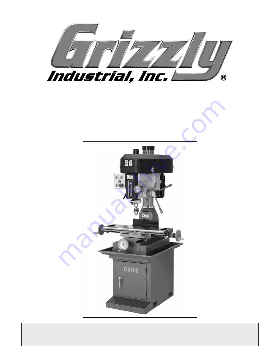
model g0705 

mill/drill w/stand

oWner's manual

Summary of Contents for G0705

Page 1: ...ed December 2010 JB Warning No portion of this manual may be reproduced in any shape or form without the written approval of Grizzly Industrial inc For models manufactured since 09 09 JB12469 printed in China MODEL G0705 Mill Drill w Stand Owner s Manual ...

Page 2: ...ng grinding tool integrity and the usage of personal protective equipment The manufacturer will not be held liable for injury or property damage from negligence improper training machine modifications or misuse Some dust created by power sanding sawing grinding drilling and other construction activities contains chemicals known to the State of California to cause cancer birth defects or other repr...

Page 3: ...ng 27 Speed Changes 28 Calculating Spindle Speed for Drilling 29 Spindle Height 30 Loading Tooling 31 Drill Chuck Arbor 32 Collet Adapters 32 Headstock Position 33 Depth Stop 33 Table Travel 34 Graduated Dials 34 SECTION 5 ACCESSORIES 35 SECTION 6 MAINTENANCE 38 Schedule 38 Cleaning and Protecting 38 Lubrication 39 SECTION 7 SERVICE 41 Troubleshooting 41 Gibs 43 Leadscrew Backlash 44 SECTION 8 WIR...

Page 4: ...chine may not exactly match the manual If you find this to be the case and the dif ference between the manual and machine leaves you in doubt check our website for the latest manual update or call technical support for help Before calling find the manufacture date of your machine by looking at the date stamped into the machine ID label see below This will help us determine if the manual version yo...

Page 5: ...b G Fine Downfeed Handwheel H Column I Table J Longitudinal Handwheel K Table Stop L Cross Travel Lock M Longitudinal Travel Lock N Cabinet Stand O Mounting Bolt Hole P Cabinet Door Q Cross Travel Handwheel R Chuck S Spindle T Depth Stop U Quill Lock Lever V Depth Scale W Headstock Elevation Crank A B C D E F G J J K L M N O P Q H I R S T U V K M W Detail of left side of machine ...

Page 6: ...8 3 8 x 17 3 4 in Shipping Dimensions Carton 1 Type Plywood Content Machine Weight 683 lbs Length Width Height 38 x 30 x 46 in Carton 2 Type Cardboard Content Stand Weight 99 lbs Length Width Height 29 x 18 x 22 in Electrical Power Requirement 220V Single Phase 60 Hz Minimum Circuit Size 30A 110V 15A 220V Switch Front Mounted Forward Reverse Switch with Emergency Stop Switch Voltage 220V Cord Leng...

Page 7: ...ndle Speeds 140 2436 RPM Table Info Table Length 28 3 4 in Table Width 8 1 4 in Table Thickness 2 1 2 in No Of T Slots 3 T Slots Width 5 8 in T Slots Height 1 in T Slots Centers 2 1 2 in Stud Size 1 2 in x 2 1 8 in Spindle Info Spindle Taper R 8 Spindle Sleeve Diameter 2 95 in End Milling Cap 3 4 in Face Milling Cap 3 in Draw Bar Diameter 7 16 in Draw Bar TPI 20 Draw Bar Length 17 11 16 in Spindle...

Page 8: ...el G0705 Features Front mounted digital display Calibrated depth stop Fine feed downfeed control graduated in 0 001 in Coolant trough Replaceable brushes on universal motor Quill moves 0 108 in per revolution of fine feed handwheel Table moves 0 100 in per revolution of handwheel Accessories Included Drill chuck 1 16 1 2 in with MT 3 spindle taper Tool box Chuck key Drift Oil bottle Hex wrenches L...

Page 9: ...WEARING PROPER APPAREL Do not wear clothing apparel or jewelry that can become entangled in moving parts Always tie back or cover long hair Wear non slip footwear to avoid accidental slips which could cause a loss of workpiece control HEARING PROTECTION Always wear hear ing protection when operating or observiing loud machinery Extended exposure to this noise without hearing protection can cause p...

Page 10: ...poorly lit areas Keep work area clean dry and well lighted to mini mize risk of injury Safety Instructions for Machinery APPROVED OPERATION Untrained operators can be seriously hurt by machinery Only allow trained or properly supervised people to use machine When machine is not being used dis connect power remove switch keys or lock out machine to prevent unauthorized use especially around childre...

Page 11: ...promptly Put away adjust ment tools after use DISCONNECT POWER Make sure the mill is turned off disconnected from its power source and all moving parts have come to a complete stop before starting any inspection adjustment or maintenance procedure AVOIDING ENTANGLEMENT Keep loose cloth ing articles such as sleeves belts or jewelry items away from the mill spindle Never wear gloves when operating t...

Page 12: ...sure it is connected to a power supply circuit that meets the requirements in the following section For your own safety and protection of property consult a qualified electrician if you are unsure about wiring practices or electrical codes in your area Note The circuit requirements listed in this man ual apply to a dedicated circuit where only one machine will be running at a time If this machine ...

Page 13: ...ed In the event of certain malfunctions or breakdowns grounding reduces the risk of electric shock by providing a path of least resistance for electric current Figure 3 Typical 5 20 plug and receptacle Grounding Prong Hot Neutral 5 20 PLUG GROUNDED 5 20 RECEPTACLE Figure 2 Typical 6 15 plug and receptacle Grounding Prong Current Carrying Prongs 6 15 PLUG GROUNDED 6 15 RECEPTACLE Serious injury cou...

Page 14: ... label them before removing to ensure that they will be replaced in the proper locations Refer to SECTION 8 WIRING starting on Page 45 for detailed wir ing diagrams L 1 L L L L L L L L 4 3 7 7 6 6 4 4 3 2 2 4 4 8 8 4 4 7 5 5 5 5 N N N N N N N N N PE V2 V1 U2 U1 V2 V2 V1 V1 2T1 14NO CONTACTOR SIEMENS KM1 CONTACTOR SIEMENS KM2 22NC 32NC 44NO 13NO 21NC 31NC 43NO 6T3 A2 A1 A1 4T2 1L1 5L3 3L2 2T1 14NO ...

Page 15: ... from its termi nals then remove the lamp 8 Install the 110V indicator lamp from the Model G0705 110V Conversion Kit in place of the lamp you removed in Step 7 9 Connect the wires you removed in Step 7 to the corresponding terminals on the 110V indi cator lamp The wiring is the same for 110V and 220V Figure 7 Contactor release tab location Gray Tab Hot Hot Ground 6 20 Plug 220 VAC Ground Neutral H...

Page 16: ...ires while you do so Figure 9 Changing motor jumper positions 14 Install a NEMA 5 20 plug such as the one shown in Figure 3 onto the power cord as illustrated in Figure 10 Refer to SECTION 8 WIRING starting on Page 45 for detailed wiring diagrams 12 Place both of the jumpers into the 110V loca tion shown in Figure 8 13 Replace the screws you removed in Step 11 making sure all wires are secured in ...

Page 17: ...acked when it left our warehouse If you discover the machine is damaged after you have signed for delivery please immediately call Customer Service at 570 546 9663 for advice Save the containers and all packing materials for possible inspection by the carrier or its agent Otherwise filing a freight claim can be difficult When you are completely satisfied with the condi tion of your shipment you sh...

Page 18: ...mblies 2 T Bolt M14 2 x 55 2 Flat Washer 14mm 2 Hex Bolt M14 2 2 H Drill Chuck Key 1 I Drift Key 1 J Collet Adapter R8 to MT 3 1 K Collet Adapter MT 3 to MT 2 1 L Bottle For Oil 1 Not Shown Hex Wrenches 3 4 5mm 1 Each Hex Bolts M10 1 25 x 140 4 Flat Washers 10mm 4 Lock Washers 10mm 4 Open End Combo Wrench 17 19mm 1 Hex Bolts M12 1 75 x 40 4 Hex Nuts M12 1 75 4 Cap Screws M6 1 x 16 3 Flat Washers 6...

Page 19: ...e off the surfaces If your cleaner degreas er is effective the rust preventative will wipe off easily Note To clean off thick coats of rust preven tative on flat surfaces such as tables use a PLASTIC paint scraper to scrape off the majority of the coating before wiping it off with your rag Do not use a metal scraper or you may scratch your machine 4 Repeat Steps 2 3 as necessary until clean then c...

Page 20: ... is important for safe operation and the longevity of its components For best results operate this machine in a dry environment that is free from excessive moisture hazardous chemi cals airborne abrasives or extreme conditions Extreme conditions for this type of machinery are generally those where the ambient temperature range exceeds 41 104 F the relative humidity range exceeds 20 95 non condensi...

Page 21: ...Lb Capacity G7160 4 3 4 Dia 8000 Lb Capacity G7161 6 1 4 Dia 25 000 Lb Capacity Option 3 Mount the machine to the floor This ensures that the machine will not move dur ing use maximizing safety Because this is an optional step and floor materials may vary this type of hardware is not included with the machine Read through the following two pages to better understand the options and determine the o...

Page 22: ...g feet then level the cabinet with shims and the use of a precision level Lag shield anchors with lag bolts and anchor studs Figure 17 are two popular methods for anchoring an object to a concrete floor We sug gest you research the many options and methods for mounting your machine and choose the best that fits your specific application Figure 17 Typical fasteners for mounting to concrete floors N...

Page 23: ...xisting workbench it must be securely attached to the workbench The strongest mounting option is a Through Mount where holes are drilled all the way through the workbench and hex bolts washers and hex nuts are used to secure machine to the work bench Machine Base Workbench Bolt Flat Washer Flat Washer Lock Washer Hex Nut Figure 18 Example of a through mount setup Machine Base Workbench Lag Screw F...

Page 24: ...o the column as possible to help balance the machine during moving 3 Place lifting straps under the head of the machine as shown in Figure 21 then con nect them to a forklift Be sure that the straps connect to the forklift far enough apart that they are not putting pressure on the belt cover When using power lifting equipment make sure the equipment is safe fully operational and adequately rated f...

Page 25: ...ting on Page 41 If you cannot find a remedy contact our Tech Support at 570 546 9663 for assistance To test run the machine 1 Make sure you understand the safety instruc tions at the beginning of the manual and that the machine is set up properly 2 Make sure all tools and objects used during setup are cleared away from the machine 3 Connect the machine to the power source 4 Push the EMERGENCY STOP...

Page 26: ...related parts and may void the warranty NOTICE DO NOT leave the area while break in pro cedure is under way You must be ready to stop the machine if any problem occurs 6 Press the STOP button to stop the machine Allow the spindle to stop rotating before pro ceeding 7 Repeat Step 5 with the REVERSE button The spindle should rotate in the opposite direction 8 Press the EMERGENCY STOP button to stop ...

Page 27: ... opera tor a basic understanding of how this machine operates the big picture view of normal opera tions on this machine Key concepts touched on here are covered in greater detail in later subsec tions This overview is not intended to be a set of detailed instructions To complete a typical operation the operator does the following 1 Loosens the vertical travel locks then adjusts the headstock heig...

Page 28: ... spindle travel Figure 24 Spindle controls Locking Knob Fine Downfeed Handwheel Quill Downfeed Levers 8 For milling operations loosens the quill lock lever and uses the quill feed lever or the fine feed knob to set the cutting tool height according to the workpiece Then presses the FORWARD or REVERSE button to start the spindle and uses the table handwheels to move the table so the cutter removes ...

Page 29: ... repositioning Figure 25 Table travel controls Longitudinal Travel Handwheels Table Locks Travel Stops Cross Travel Handwheel Reverse Button Moves the spindle in a counter clockwise direction Forward Button Moves the spindle in a clock wise direction Power Indicator Illuminates when power is sup plied to the machine Stop Button Stops spindle rotation Emergency Stop Button Cuts power to the machine...

Page 30: ...Iron soft 80 Cast Iron hard 50 Mild Steel 90 Cast Steel 80 Alloy Steel hard 40 Tool Steel 50 Stainless Steel 60 Titanium 50 Plastics 300 800 Wood 300 500 Note For carbide cutting tools double the cut ting speed These values are a guideline only Refer to the MACHINERY S HANDBOOK for more detailed information Figure 29 Cutting speed table for HSS cutting tools Before calculating the spindle speed fo...

Page 31: ...Open the belt cover then loosen the two idler cap screws Figure 31 that hold the idler pul ley in place so it can move freely Figure 31 Pulley system 4 With the center and rear pulleys loose move the V belts to the corresponding position for the desired speed see chart below 5 Loosen the motor locking lever and allow the spring to tighten the rear V Belt then re tighten the motor locking lever 6 T...

Page 32: ...ass Aluminum Mild Steel 3 8 1 2 1200 1000 5 8 1 800 600 Using the Drill Bit Speed Chart The chart shown in Figure 33 is intended as a guide only Always follow the manufacturer s speed recommendations if provided with your drill bits cutters or hole saws Exceeding the recommended speeds may be dangerous to the operator The speeds shown here are intended to get you started The optimum speed will alw...

Page 33: ... Figure 35 The Model G0705 has coarse downfeed levers and a micro adjustment handwheel To operate the downfeed levers simply pull forward and down on the lever nearest you The spindle will go down until you stop pulling or until it hits the depth stop To operate the micro adjustment handwheel 1 Tighten the locking knob located on the cen ter of the hub for the downfeed levers Figure 34 This transf...

Page 34: ...Tooling To remove tooling 1 DISCONNECT MACHINE FROM POWER 2 Loosen but do not remove the drawbar 3 Hold the tooling with a shop towel to prevent it from dropping completely out of the machine Tap on the top of the drawbar with a brass hammer to loosen the collet arbor from the spindle as shown in Figure 37 Figure 37 Collet removal 4 Unthread the drawbar until it is free from the tooling Remove cut...

Page 35: ... good fit Note While it may not seem like there is anything keeping the drill chuck in place the MT 3 taper fit provides a strong bond and will hold the drill chuck tightly The Model G0705 includes two adapters that will allow the use of MT 3 and MT 2 tooling A drift key is also included to aid in the separation of the adapters and any installed tooling Use the adapters as necessary to fit the too...

Page 36: ...he depth stop leadscrew until the top of the indicator plate is level with your desired depth as listed on the scale to the left or right Figure 41 The headstock height and rotation on the Model G0705 can be adjusted for various applications For increased quill rigidity and reduced vibrations which will produce the best results keep the quill fully retracted and set the headstock as low as possibl...

Page 37: ...ient movements Each dial can be reset or locked with the thumbscrew attached to it Example Suppose you want to drill a series of holes in a workpiece at 0 625 centers After locating and drilling the first placement you can set the dial of the appropriate axis to zero while holding the handwheel Move the table 0 625 Drill the next hole and proceed as above Figure 44 Graduated dial Graduated Dial Th...

Page 38: ...ve action locks very low profiles 10 second vernier scales gear drives with oil immersion and satin chrome dials See the current Grizzly catalog for full specifica tions Features 4 330 overall height horizontal 6 750 height to center hole vertical 3 Morse Taper 0 465 T slot width and 117 lb approximate shipping weight Figure 46 G9299 10 Yuasa Type Rotary Table G1076 52 PC Clamping Kit This clampin...

Page 39: ...owing sizes 1 8 3 16 1 4 5 16 3 8 7 16 1 2 5 8 and 3 4 Figure 51 G9765 9 PC Ball End Mill Set G5641 1 2 3 Blocks G9815 Parallel Set H5556 Edge Finder Set Figure 52 G5641 1 2 3 Blocks G9815 Parallel Set and H5556 Edge Finder Set G5641 G9815 H5556 H8370 Power Feed for Mills If you want to get the most out of your mill you really need a power feed This power feed comes with everything required to sta...

Page 40: ...ted properly Biannual Check Lubricate table leadscrews Schedule Metal chips left on the machine that have been soaked with water based coolant will invite oxi dation and a gummy residue buildup around the moving parts Use a brush and shop vacuum to remove chips and debris from the working sur faces of the mill Never blow off the mill with com pressed air as this will force metal chips deep into th...

Page 41: ...idue with a cloth G Ways Periodically lubricate the ways with Mobil Vactra 2 or way oil Lubrication Figure 54 Ball oiler locations A B F F F G D C E E Table Leadscrews Every six months or more frequently under heavy use clean and lubricate the leadscrews Items Needed Qty Mobil Vactra 2 or ISO 68 Equivalent 1 Stiff Bristled Nylon Brush for Cleaning 1 Mineral Spirits As needed for cleaning Shop Rags...

Page 42: ...d Changes on Page 29 to loosen the belts Remove them from the pulleys then install new V belts V Belts Pulley Deflection Pulley Figure 57 Belt tension 1 4 5 Using the longitudinal handwheel move the table as far to one side as possible 6 Use mineral spirits and a brush to clean as much of the oil and debris as possible off of the longitudinal leadscrew shown in Figure 56 Allow the leadscrew to dry...

Page 43: ...ct for the task 4 Motor connection is wired incorrectly 5 Motor has overheated 6 Motor bearings are at fault t7 Motor is at fault 1 Adjust feed rate cutting speed 2 Use the correct cutter for the task 3 Use smaller or sharper tooling reduce feed rate or spindle speed use cutting fluid if possible 4 Wire motor correctly for the intended voltage 5 Clean off motor let cool and reduce workload 6 Test ...

Page 44: ... extended too far down 1 Tighten down table locks Page 35 2 Tighten quill lock lever Page 31 3 Check that clamping is tight and sufficient for the job Make sure mill vice is tight to the table 4 Set spindle speed correctly Page 29 or use a slower feed rate 5 Fully retract spindle and lower headstock This increases rigidity Table is hard to move 1 Table locks are tightened down 2 Chips have loaded ...

Page 45: ... or unloading return spring pres sure Failure to use such precautions may result in personal injury Do not completely remove the cover If you remove the spring cover the spring will uncoil rapidly and create a risk of laceration or impact injury Wear gloves and safety glasses during this procedure Return Spring The spring tension for automatic quill recoil has been pre set at the factory It should...

Page 46: ...s in small increments Over tightening to attempt to reduce backlash to less than 0 003 is impractical and will add unneces sary wear to both the leadscrews and the adjust ers Figure 61 X axis leadscrew adjuster Leadscrew Adjuster 2 Tighten the adjustment screw 3 Test the adjustment by turning one of the side handwheels You should detect less than 0 008 of play 4 Put on gloves and pull the spring c...

Page 47: ...ck all wires dis connected or connected during any wiring task to ensure tight connections CIRCUIT REQUIREMENTS You MUST follow the requirements at the beginning of this man ual when connecting your machine to a power source WIRE COMPONENT DAMAGE Damaged wires or components increase the risk of serious per sonal injury fire or machine damage If you notice that any wires or components are damaged w...

Page 48: ...s Recommended PE V2 V1 U2 U1 U2 V1 V2 Z1 W1 Z2 W2 U1 U2 V1 V2 Z1 W1 Z2 W2 U1 To Electrical Box Start Capacitor 150 MFD 250 VAC Run Capacitor 20 MFD 450 VAC 110V Terminal Block Jumper Position Wire positions are the same for 110V 220V To Electrical Box Cord Rewired for 110V Motor 220V G0705 Wiring Diagram ...

Page 49: ...4 13NO 21NC 31NC 43NO 6T3 A2 4T2 1L1 5L3 3L2 V1 U2 U2 U2 U1 PE 1 1 1 PE GND GND Contactor Information For 220V Contactor Type 3TB41 22 OX Coil Voltage 220V 60Hz 1PH SIEMENS For 110V Contactor Type 3TB41 22 OX Coil Voltage 110V 60Hz 1PH SIEMENS Contactor is wired the same for 110V 220V To Motor To Plug Control Panel Viewed From Behind Electrical Box 12A FUSE Indicator Light Type XDJ2 J 220V AC Indi...

Page 50: ...13 14 15 16 17 18 19 20 21 22 23 23 1 23 2 23 3 23 4 23 5 23 3 24 25 26 27 28 29 31 32 33 35 37 39 40 41 42 43 44 45 46 47 48 49 51 52 53 54 55 56 57 58 59 60 61 61 62 62 63 63 64 65 66 67 68 69 70 71 72 74 75 76 77 78 79 80 81 82 83 84 85 86 88 89 90 91 92 93 93 1 93 2 93 3 93 4 93 5 94 94 95 96 97 97 98 99 100 101 102 113 113 1 SECTION 9 PARTS ...

Page 51: ...E 10 P0705010 QUILL CLAMP 28 P0705028 FEED ADJUST KNOB M10 1 5 X 45 11 P0705011 QUILL ASSEMBLY 29 P0705029 LEVER 11 1 P0705011 1 SPANNER NUT 31 P0705031 WORM SHAFT COVER 11 2 P0705011 2 TOOTHED SPINDLE WASHER 32 PCAP02 CAP SCREW 10 24 X 3 8 11 3 P30206 TAPERED ROLLER BEARING 30206 33 P0705033 MICRO ADJUST INDICATOR SET 11 4 P0705011 4 SPINDLE SLEEVE MT 3 35 P0705035 HANDWHEEL ASSEMBLY 11 5 P30207 ...

Page 52: ...TOR 2HP 110 220V 1 PH 62 PW14 FLAT WASHER 5 8 93 1 P0705093 1 MOTOR JUNCTION BOX 63 PN04 HEX NUT 5 8 11 93 2 PC150D S CAPACITOR 150M 250V 1 5 8 X 3 1 4 64 P0705064 HEADSTOCK WRENCH 93 3 PC20B R CAPACITOR 20M 450V 1 5 8 X 3 1 4 65 P0705065 LOCK HANDLE M8 1 25 X 25 93 4 P0705093 4 MOTOR FAN 66 P0705066 FRONT COVER PLATE ASSEMBLY 93 5 P0705093 5 MOTOR FAN COVER 67 PCAP04 CAP SCREW 1 4 20 X 1 2 94 PW0...

Page 53: ...reakdown 201 202 203 204 205 205 205 205 205 206 206 207 207 207 209 210 211 212 212 212 213 216 217 217 218 218 219 219 220 221 222 223 224 225 226 226 227 227 228 228 229 230 231 232 233 234 246 235 236 237 238 240 241 242 243 244 244 245 247 ...

Page 54: ...10 P0705210 DOWEL PIN 234 P0705234 BASE 211 P0705211 LEFT FLANGE 235 P0705235 CROSS LEADSCREW ASSEMBLY 212 PCAP03 CAP SCREW 5 16 18 X 1 236 P0705236 COLUMN BASE 213 P0705213 LONGITUDINAL HALF NUT 237 P0705237 ELEVATION RACK 216 P0705216 LONGITUDINAL LEADSCREW 238 P0705238 COLUMN CAP 217 P0705217 KNURLED THUMBSCREW M5 8 X 12 240 P0705240 COLUMN RING 218 P0705218 INDICATOR PLATE 241 PB64 HEX BOLT 5 ...

Page 55: ...NC 31NC 43NO 6T3 A2 A1 A1 4T2 1L1 5L3 3L2 2T1 14NO 22NC 32NC 44NO 13NO 21NC 31NC 43NO 6T3 A2 4T2 1L1 5L3 3L2 Electrical Box Control Panel Viewed From Behind 12A 301 302 303 303 304 305 306 307 308 309 310 311 Electrical Components Breakdown and List REF PART DESCRIPTION REF PART DESCRIPTION 301 P0705301 ELECTRICAL BOX ASSEMBLY 307 P0705307 EMERGENCY STOP BUTTON 302 P0705302 TERMINAL BLOCK ASSEMBLY...

Page 56: ...emoved or becomes unreadable REPLACE that label before using the machine again Contact Grizzly at 800 523 4777 or www grizzly com to order new labels REF PART DESCRIPTION REF PART DESCRIPTION 401 P0705401 MACHINE ID LABEL 406 PPAINT 11 PUTTY TOUCH UP PAINT 402 PLABEL 11B SAFETY GLASSES LABEL 407 P0705407 CUTTER WARNING LABEL 403 PLABEL 55A ENTANGLEMENT LABEL 408 PPAINT 1 GREEN TOUCH UP PAINT 404 P...

Page 57: ...r metalworker ____ 0 2 Years ____ 2 8 Years ____ 8 20 Years ____20 Years 6 How many of your machines or tools are Grizzly ____ 0 2 ____ 3 5 ____ 6 9 ____10 7 Do you think your machine represents a good value _____Yes _____No 8 Would you recommend Grizzly Industrial to a friend _____Yes _____No 9 Would you allow us to use your name as a reference for Grizzly customers in your area Note We never use...

Page 58: ...D LINE FOLD ALONG DOTTED LINE GRIZZLY INDUSTRIAL INC P O BOX 2069 BELLINGHAM WA 98227 2069 Place Stamp Here Name_______________________________ Street_______________________________ City______________State______Zip______ Send a Grizzly Catalog to a friend ...

Page 59: ...e tried in the State of Washington County of Whatcom We shall in no event be liable for death injuries to persons or property or for incidental contingent special or consequential damages arising from the use of our products To take advantage of this warranty contact us by mail or phone and give us all the details We will then issue you a Return Number which must be clearly posted on the outside a...

Page 60: ...Buy Direct and Save with Grizzly Trusted Proven and a Great Value Since 1983 ORDER 24 HOURS A DAY 1 800 523 4777 Visit Our Website Today For Current Specials ...

Reviews: