


Instructions – Parts List
GRACO INC.
P.O. BOX 1441
MINNEAPOLIS, MN
55440–1441
Copyright 2002, Graco Inc. is registered to I.S. EN ISO 9001
120 VAC, 15A
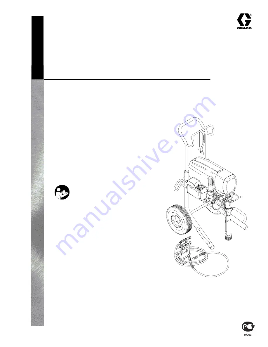
ULTRA
R
MAX 795
Airless Paint Sprayer
3000 psi (21 MPa, 210 bar) Maximum Working Pressure
Model 232140, Series A
Basic sprayer on upright cart without
hose or gun
Model 232141, Series A
Complete sprayer on upright cart with hose,
gun, RAC IV
DripLess
Tip Guard
and SwitchTip
U.S. PATENT No. 4,323,741; 4,397,610
PATENTED 1983, CANADA
AND OTHER PATENTS PENDING
308800F
Important Safety Instructions
Read all warnings and instructions in this manual.
Save these instructions.
Related Manuals
Displacement Pump
308798
. . . . . . . . . . . . . . . . .
Spray Gun
307614
. . . . . . . . . . . . . . . . . . . . . . . . .
Spray Tip
308644
. . . . . . . . . . . . . . . . . . . . . . . . . . .
7706A


