Grace Q'nique 21, Instruction Manual
Looking for a reliable, high-performance longarm quilting machine? Look no further than the Grace Company Q'nique 21! Enhance your quilting experience with the Q'nique 21's precise stitching and advanced features. Need assistance? Download the free service manual from manualshive.com to ensure optimal performance and maximize the potential of your quilting masterpiece.
Share
Download


Reviews:
No comments
Related manuals for Q'nique 21

HD2200
Brand: Janome Pages: 48

VN1715
Brand: Viper Pages: 9

MO-6900G Series
Brand: JUKI Pages: 4

GF-1117 Series
Brand: Garudan Pages: 30

Lavina 25L HV Pro
Brand: Superabrasive Pages: 29

Code-a-phone 700
Brand: Ford Pages: 52

Autopax PAX200H
Brand: Quasar Pages: 76

WLEL31216.0
Brand: Weslo Pages: 24

TAD-798
Brand: Radio Shack Pages: 24

MC6600
Brand: Janome Pages: 49

HZL-E61
Brand: JUKI Pages: 24

HZL-30Z
Brand: JUKI Pages: 44
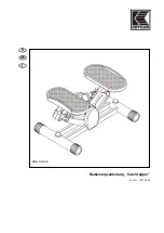
07874-950
Brand: Kettler Pages: 12

SV-520
Brand: ISM Pages: 33

500 CLUB
Brand: ELNA Pages: 31

LASERFAX 920
Brand: Philips Pages: 2

HFC 242
Brand: Philips Pages: 20

MF-JET 500
Brand: Philips Pages: 36


