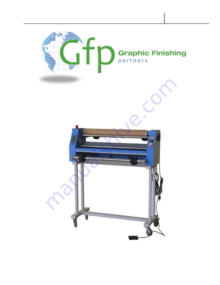
background image

Gfp 230 C 

June 2012 


OPERATING MANUAL  Gfp 230 C


Please read this manual carefully before operating! 


Unpacking, assembly, and operating videos are available at 

www.gfpsmoothstart.com  

Summary of Contents for 230 C

Page 1: ...Gfp 230 C June 2012 1 OPERATING MANUAL Gfp 230 C Please read this manual carefully before operating Unpacking assembly and operating videos are available at www gfpsmoothstart com...

Page 2: ...machine stand 12 D Set Machine on stand 12 E Attach supply support brackets 13 10 Additional installation items 14 11 Loading bottom Media or Kraft Paper rolls 14 12 Installing take up reel 15 13 Load...

Page 3: ...l you will find important safety messages regarding the product Read these instructions carefully failure to comply with the following safety procedures could result in serious injury WAR I G Do not a...

Page 4: ...machine must have reliable earth wire to ensure the safety of the machine during operations Contact an electrician should the attachment plug provided with the laminator not match the receptacles at y...

Page 5: ...igid materials in between the two rubber rollers Do not attempt to laminate items that exceed total recommended material thickness of the unit Do not place foreign object inside the machine Do not cut...

Page 6: ...t put burrs sharp knives or extra thick and hard materials in between the rollers Do not leave objects like tools rulers knives etc on the working panels or the side cabinets to avoid their being roll...

Page 7: ...pply shaft 3 Brake assembly 13 Brake assembly 4 Feed tray 14 Right side frame 5 Nip safety guard 15 Roller pressure adjustment 6 Left side frame 16 Power cord 7 Emergency stop switch 17 Control panel...

Page 8: ...230 C June 2012 8 7 Control Panel 1 Run foot pedal switch 2 Speed Adjustment 3 Forward reverse switch ote The machine does not have continuous reverse Reverse can only operate using the pedal switch 2...

Page 9: ...n Machine Crate Part Quantity Part Quantity Main Machine 1 Hex Screw 8mm x 80 8 Rewind tube 1 Hex Screw 5mm x 12 16 Support brackets for shafts 4 Plain washer 8 8 Supply shafts 2 Plain washer 5 16 Bra...

Page 10: ...C June 2012 10 9 Installation A Uncrate the machine 1 Remove screws around the base of the crate including corner supports 2 Lift crate straight up and off the skid 3 Stand legs are inside behind the...

Page 11: ...kid 1 Remove plastic cover and accessory box 2 Remove supply shafts and stand cross members from the crate base by loosening the screws and hold down straps 3 Remove four 4 anchor bolts holding machin...

Page 12: ...d lock washer Flat washer against the stand 3 Start all screws by hand before tightening 9 D Set machine on stand 1 Remove machine from the bottom supports of the shipping crate 2 Lift machine onto su...

Page 13: ...pply shaft 1 Attach Top and Bottom supply brackets to each side frame using 16 5mm x12 screws 2 Slide brakes on round supply shafts 3 Insert supply shafts onto top and bottom supply brackets 1 Upper s...

Page 14: ...bly to the supply shaft 4 Position the supply roll in the middle of the supply shaft and measure the distance from one side of the roll to the side frame You ll use this measurement when loading the t...

Page 15: ...core stop clip positioned on top of the rewind tube Note Pay attention to the direction of the core stop clip or the application will be affected 4 The rewind tube is driven by friction The friction...

Page 16: ...m the roll to the side frame as the bottom roll in section 11 to align the top and bottom rolls 5 Fasten the screws for film core adaptor Note there should be 1 8 clearance between the positioning and...

Page 17: ...e paper tube on the top rewind tube OTE Slide film cutter between the paper liner and film to cut liner only Be careful not to cut the top heat roller 6 Use foot pedal to advance the film web until th...

Page 18: ...ing voltages before operations Do not use incorrect power supply Do not use damaged wires or sockets If abnormal conditions occur switch off the power supply first 2 Turn power to ON with the rear pow...

Page 19: ...film section 13 Turn the pressure adjusting hand wheel to lift up the upper roller Select a piece of Gatorboard or other PVC mounting board the width of the film web to use as a sled under the print...

Page 20: ...nwinding from the BOTTOM of the roll Thread both rolls through machine see Threading film section 13 Press run Feed single sheets continuously 17 C Media from a roll Load a roll of laminating film on...

Page 21: ...oard half way through the roller and stop Insert mounting board to be coated and depress foot switch After the last board insert leader board to keep adhesive from contacting the rollers 18 B Mounting...

Page 22: ...er pressure to low 2 Dust on the surface of the print 1 Increase nip roller pressure 2 Clean print surface before lamination Poor film adhesion on one side 1 Nip roller pressure on the two sides is no...

Page 23: ...peed 4 Ft min Unwinds Top and bottom Film core size 3 Liner take up Direct drive Pressure adjustment Single Hand wheel Tension adjustment Dual brakes Power Supply 110 v 0 3 amp Power Consumption 30 W...

Page 24: ...oduct discloses to Gfp s satisfaction that such defects actually exist and were not caused by misuse neglect attempt to repair unauthorized alteration or modification incorrect line voltage fire accid...

Reviews: