


GV-NET/IO Card V3.1
The GV-NET/IO provides 4 inputs and 4 relay outputs. The new version of GV-
NET/IO Card supports both DC and AC output voltages, and provides a USB port as
well.
1
2
3
4
RJ-11 to DB9 Cable x1
20-pin Ribbon Cable (4 Connectors) x1
GV-NET I/O Card x1
4-pin to 4-pin Mini Power Cable x 1
Packing List
Specifications
Input
Output
Input Signal
Input
Relay Output
Relay Status
Relay Capacitance
9~30V AC/DC
4
4
Normal Open
30V DC, 3A
USB
Connection
125 / 250V AC, 3A
Communication
RS-485, USB, RS-232
Environmental Conditions 0~50 degree C , 5%~95% (non-condensing)
Dimensions
99 (W) x 90 (H) mm
Address 1-4
Mode Switch
I/O Box Mode
Interface
RJ-11 to DB9
RJ-11 to USB
3-pin internal USB to internal USB
NET/IO Card Mode
Without GV-Video Capture Card
RS-232
Connection
5
RJ-11 to USB Cable x 1
3-pin Internal USB Cable x 1
6
7
Installation Guide x 1
With GV-Video Capture Card
GV Video Capture Card
RS-485 +
RS-485 -
Relay Out 1
Relay Out 2
Relay Out 3
Relay Out 4
Com
Input 1
Input 2
Input 3
Input 4
Ground
4-pin to 4-pin Mini
Power Cable
6
GV-NET I/O Card
1
ON
20-pin
Ribbon Cable
2
1
ON
1
2
ON
1
ON
30V DC, 3A
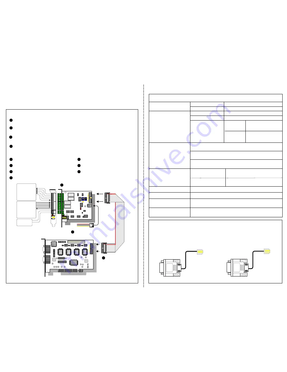
Important:
The supplied RJ-11 to DB9 Cable of older versions is not compatible
with the GV-NET/IO Card V3.1.
PC
Version 3.1
With a PC Mark
Older Versions
Without a PC Mark
1
2
3
It can switch between two modes, NET/IO Card Mode and I/O Box Mode, which
expands its
capability
.
Up to 4 GV-NET/IO Cards can be chained together when it is on the I/O Box
mode.
A USB port is provided for PC connection, and it is used with 30 DC output
voltage.
Key Features
4
It can act as an independent device when it is on the I/O Box mode.


