General Standards Corporation PCI-SIO4, User Manual
The General Standards Corporation PCI-SIO4 User Manual is essential for understanding the features and functions of this product. Download the manual for free from our website to ensure smooth installation and operation of your PCI-SIO4 device. Get the most out of your product with this comprehensive manual.
Share
Download


Reviews:
No comments
Related manuals for PCI-SIO4

IMAQ PCI-1408
Brand: National Instruments Pages: 61

00054115
Brand: Hama Pages: 36

DynaPAD
Brand: Magtek Pages: 2

RS-232
Brand: Kraun Pages: 8
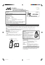
KS-USB10
Brand: JVC Pages: 2

SC005
Brand: SWEEX Pages: 4

ADCFAEU3
Brand: Addonics Technologies Pages: 2

FAST TRAK S150
Brand: Promise Technology Pages: 74

AR82
Brand: Nordic ID Pages: 20

HH53
Brand: Nordic ID Pages: 19

APCIe-040
Brand: Addi-Data Pages: 31

E34
Brand: Sonnet Pages: 14

V6800GS-512A
Brand: Diablotek Pages: 1

PC-DIG4
Brand: Sonifex Pages: 20

GTX 460 1024MB GS-GLH
Brand: Gainward Pages: 2

USB 2.0, 4+1 Port PCI Add-On card
Brand: Digitus Pages: 6

UHB-CR3-02
Brand: Gembird Pages: 10

SPC-2010
Brand: Gembird Pages: 13


