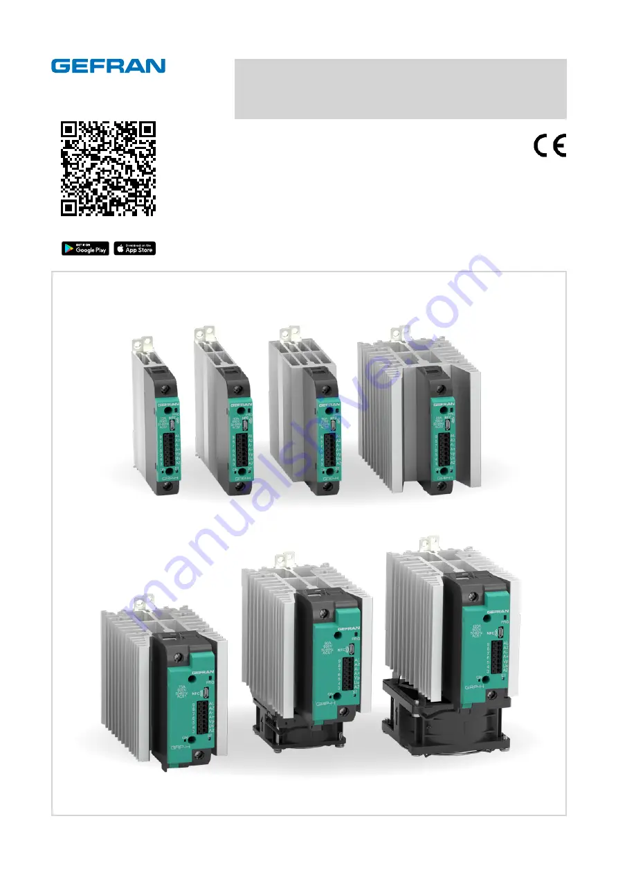
background image

For all specifics, documentation 

and  App for smarphone

CONFIGURATION AND
PROGRAMMING MANUAL

code: 81906_MAN_GRP-H_02-2022_ENG

STATIC POWER UNITS WITH PARTIAL LOAD BREAK,
LOGIC/ANALOG COMMAND AND IO-LINK COMMUNICATION

GRP-H 

15/25/30/40/50/60/75/90/120A

81906_MAN_GRP-H_02-2022_ENG

Summary of Contents for GRP-H120A

Page 1: ...p for smarphone CONFIGURATION AND PROGRAMMING MANUAL code 81906_MAN_GRP H_02 2022_ENG STATIC POWER UNITS WITH PARTIAL LOAD BREAK LOGIC ANALOG COMMAND AND IO LINK COMMUNICATION GRP H 15 25 30 40 50 60...

Page 2: ...81906_MAN_GRP H_02 2022_ENG_pag 2...

Page 3: ...y meter 1 25 4 1 4 6 Consumed energy meter 2 26 4 1 4 7 Energy meter reset 26 4 1 5 Digital input 26 4 1 5 1 Digital input 1 function 26 4 1 5 2 Digital input 1 type 27 4 1 5 3 Digital input 2 functio...

Page 4: ...user 51 4 8 1 7 Hardware card recognition 52 4 8 1 8 Hardware card recognition 1 52 4 8 1 9 Options installed 52 5 IO Link 53 5 1 IO Link 53 5 2 IO LINK INSTALLATION AND ELECTRICAL CONNECTIONS 53 5 2...

Page 5: ...nel closed CONTROL The GRP H series can be controlled in three different ways based on the options chosen 1 Logic signals in V DC OnOff mode 2 Analogue signal configurable as 0 5V 0 10V 0 20mA 4 20mA...

Page 6: ...one device and another at least 100mm Horizontal distance between one device and another at least 20mm in the event of installa tion at shorter distances see derating curves Make sure that the cable d...

Page 7: ...4 01 n4 5 0 18 4 5 0 18 4 5 0 18 4 3 0 17 4 3 0 17 4 3 0 17 4 3 0 17 4 3 0 17 4 3 0 17 70 2 76 137 8 5 4 4 3 0 17 mm mm mm mm mm mm mm mm mm mm mm mm mm mm 60A 75A 15 25A 30A 40 50A 60A 90A ALL FAN OP...

Page 8: ...3 4 06 110 4 33 UNLOCKING SLIT PE SCREW M5x8 MAX M5x0 31 MAX mm PE WIRE AWG10 5mmq mm mm mm mm mm 1 2 1 2 SCREW DRIVER DIN rail coupling sequence DIN rail release sequence Use of a slotted screwdriver...

Page 9: ...06 110 6 4 33 0 69 4 3 0 17 PE SCREW M5x8 MAX M5x0 31 MAX PE WIRE AWG10 5mmq mm mm mm mm mm mm mm TOP VIEW mm mm GRP 15 60A PROGRAM BUTTON USB NFC SCR ON LED GREEN LED GREEN RUN LED RED ALARM LED BLUE...

Page 10: ...nal connector analogue input 3 A2 Power GND 4 Us V DC power supply GRP H power supply Range from 10 to 30 V DC Imax 20 mA at 24V GRP H 90 120A FAN63 GRP H Fan power supply Range from 20 to 27 V DC Ima...

Page 11: ...ersioni D ingresso digitale 3 A2 Power GND 4 Us V DC power supply GRP H power supply Range from 10 to 30 V DC Imax 20 mA at 24V GRP H 90 120A FAN63 GRP H Fan power supply Range from 20 to 27 V DC Imax...

Page 12: ...scription Notes 1 L1 Line Connection 2 T1 Load Connection I version signal connector IO LINK 3 L Power GND 4 L V DC power supply GRP H power supply Range from 10 to 30 V DC Imax 20 mA at 24V GRP H 90...

Page 13: ...in the specific section GRP 1 LOAD 1 G R P 3 L O A D 3 G R P 2 L O A D 2 L1 L2 L3 V L3 PE L2 L1 L3 PE L2 L1 Load open delta Connect the control signals analog or digital on all the devices as shown i...

Page 14: ...ew type 9 2 x 8 mm M5 10 5 x 10 7 mm M5 Stripping length 11 mm 13 mm 1 Conductor section 2 Conductors section 1 x 2 5 mm2 2 x 1 5 mm2 1 x 6 mm2 2 x 4 mm2 1 x 10 mm2 2 x 6 mm2 1 x 16 mm2 2 x 10 mm2 1 x...

Page 15: ...LES 2 FIX NEW FAN BY SCREW 2 1 FIX NEW FAN BY SCREW 1 3 FIX CONNECTOR ON PCB 2 FIX NEW FAN BY SCREW 2 1 FIX NEW FAN BY SCREW 1 2 8 Fan maintenance Caution make sure that the arrow showing the directio...

Page 16: ...application can read write configuration recipes model information and diagnostic data The application allows you to open recipes on the smartphone memory read them from the device and retransmit them...

Page 17: ...application needs Caution Before commissioning the GRP device the user must ensure the parameters are set correctly to avoid damages to persons or property If you are unsure of your skills or not ful...

Page 18: ...PERATION LED on or flashing as indicated in the LED chapter LED status with key pressed Key pressed Key pressed 3 s and then released Key repeatedly pressed and released 0 2 s Key pressed 9 s and then...

Page 19: ...y key 4 1 1 2 Analogue input scale minimum limit Acronym App GF_eXpress menu Attribute Retentive U M Default Description Lo S Inputs Analog input R W s p 0 0 The parameter sets the analogue input scal...

Page 20: ...ts the time of the low pass filter on the analogue input signal min max 0 0 20 0 s 4 1 1 6 Fault Action Power Acronym App GF_eXpress menu Attribute Retentive U M Default Description FA P Controls R W...

Page 21: ...Xpress menu Attribute Retentive U M Default Description o tA Inputs CT input R W A 0 0 Current reading correction offset min max 99 9 99 9 A 4 1 2 2 Current reading low pass digital filter Acronym App...

Page 22: ...t value Acronym App GF_eXpress menu Attribute Retentive U M Default Description I tA Expert Status Current R A Current reading real time value 4 1 2 6 Current reading input value Acronym App GF_eXpres...

Page 23: ...s 2 0 Voltage reading digital filter min max 0 0 20 0 s 4 1 3 3 Voltage reading update time Acronym App GF_eXpress menu Attribute Retentive U M Default Description Ut V Inputs VT line input R W s 10 V...

Page 24: ...V Voltage reading real time value 4 1 3 7 Voltage reading input value Acronym App GF_eXpress menu Attribute Retentive U M Default Description I tVF Status R V Filtered voltage reading value 4 1 3 8 Ma...

Page 25: ...tage 4 1 4 3 Power on load Acronym App GF_eXpress menu Attribute Retentive U M Default Description Ld P Status R kW Power on load 4 1 4 4 Load impedance Acronym App GF_eXpress menu Attribute Retentive...

Page 26: ...Default Description STATUS11 Expert Status Diagnostics R W 0 Energy meter reset commands Bit Meaning 11 Ld E1 reset 12 Ld E2 reset Settings 4 1 5 1 Digital input 1 function Acronym App GF_eXpress menu...

Page 27: ...ute Retentive U M Default Description dIG 2 Inputs Digital inputs R W Digital input 2 function Options 0 Disabled input no function 1 Main command SSR When switched on the following is set model GRP H...

Page 28: ...utton according to the flow illustrated in the chapter Device configuration 3 1 4 Key on page 18 you can set The number of loads in parallel for GRP xxxx 1 xxxxx models and enable HB calibration Chang...

Page 29: ...alue set in A Hbx while the SSR control output is OFF Hb F 2 the alarm is triggered by joining functions 0 and 1 with a logical OR The A Hbx 0 setting disables both types of HB alarm by forcing the Al...

Page 30: ...Percent HB alarm setpoint of current read in HB calibration Hb P HB alarm setpoint A Hb Calibration ON Value of Ou P control outputs Value of CT input with output on I onF CT read in HB calibration Hb...

Page 31: ...d the HB alarm have disappeared the alarm remains active until a reset is triggered by a key serial line or IO Link Options 0 Disabled 1 Enabled 4 2 1 5 HB alarm functionB Acronym App GF_eXpress menu...

Page 32: ...b tr alarm threshold Acronym App GF_eXpress menu Attribute Retentive U M Default Description Hb tr Expert Status Diagnostics R A HB alarm threshold as function of power on load The Hb tr threshold val...

Page 33: ...cription ALSTATE_HB Expert Status Diagnostics R Detail of HB alarm status Calibration 4 2 1 12 Calibration command Acronym App GF_eXpress menu Attribute Retentive U M Default Description STATUS11 Expe...

Page 34: ...7 loads 93 0 8 loads 94 0 min max 0 0 100 0 4 2 1 14 Current reading in HB calibration Acronym App GF_eXpress menu Attribute Retentive U M Default Description Hb tA Alarms HB Alarm R W A 0 0 Current v...

Page 35: ...ich it is also possible to enable only a part of it SSR_SHORT SSR module shorted NO_VOLTAGE lack of line voltage NO_CURRENT for SSR module open or load interrupted The NO_CURRENT alarm is triggered wi...

Page 36: ...r IO Link Options 0 Disabled 1 Enabled 4 2 2 3 SSR_SHORT update time Acronym App GF_eXpress menu Attribute Retentive U M Default Description dG t Alarms PF Alarms R W s 10 SSR_SHORT alarm update or wa...

Page 37: ...d HB bit Meaning 0 Heater Break or Power Fault alarms 1 Heater Break alarm 2 Power Fault alarms OR of 3 4 5 3 SSR_SHORT 4 NO_VOLTAGE 5 NO_CURRENT Status 4 2 2 6 Alarm reset Acronym App GF_eXpress menu...

Page 38: ...g fan if installed With the over_heat alarm on the control disables control outputs 4 2 3 1 SSR temperature Acronym App GF_eXpress menu Attribute Retentive U M Default Description Ntc SSR Status R C S...

Page 39: ...arm event counter 2 not resettable The counters are saved in the retentive memory every hour and when the line voltage is switched off 4 3 3 3 Counter reset Acronym App GF_eXpress menu Attribute Reten...

Page 40: ...reset command Bit Meaning 15 SH c1 count reset 4 3 3 7 Max temperature value reached 1 Acronym App GF_eXpress menu Attribute Retentive U M Default Description Ntc SSR Max1 Expert Status Temperature R...

Page 41: ...us Diagnostic R W 0 Max temperature reset command 1 4 3 3 10 Number of hours of SSR operation Acronym App GF_eXpress menu Attribute Retentive U M Default Description OH c Counters R h 0 Number of devi...

Page 42: ...eak or Power Fault alarms 2 Heater Break alarm 3 Power Fault alarms 4 SSR Over Heating 5 Heater Break or Power Fault alarms or SSR Over Heating 6 Heater Break alarm or SSR Over Heating 7 Power Fault a...

Page 43: ...4 Device with partial HB option with activated calibration 2 Device with partial HB option not calibrated just installed 1 HB alarm NO_VOLTAGE or NO_CURRENT alarm 3 Mains voltage frequency alarm 4 MAN...

Page 44: ...d from the analogue input value It is possible to switch to Manual mode to deliver the power value from the Man P parameter GRP H x x I x x x x x x model Manual mode the power value to be delivered is...

Page 45: ...f operating and non operating cycles in the ratio of the power to be transferred to the load BF to variable cycle time This mode manages the power on the load through a series of conduction ON cycles...

Page 46: ...reduce the flickering of the filaments with short medium wave IR lamp loads with such loads to limit the steady state current with low power it is useful to set a minimum power limit e g Lo P 10 Exam...

Page 47: ...ngle Cycle 4 7 3 3 Softstart This type of start up can be enabled in BF PA and HSC mode for versions with type AN or I control In the case of phase control the increase in the conduction angle q stops...

Page 48: ...possible to set hd 5 0 FCT trigger in Zero Crossing with full wave with fixed cycle time that can be set in parameter Ct In case of models with trigger option GRP H x x x x x x 2 x x the default is h...

Page 49: ...in Phase Angle starts from a conduction angle and reaches 100 0 in a time set in the PS tm parameter from 0 1 to 60 0 s Soft start ends before the defined time if the power reaches the corresponding r...

Page 50: ...status Acronym App GF_eXpress menu Attribute Retentive U M Default Description STATUS3 Expert Status Diagnostic R Soft start ramp status bit Meaning 2 Phase soft start on 3 Phase soft start end 4 8 1...

Page 51: ...yy last two digits of the year of manufacture ww week of production nnnn sequential number in the week of production 4 8 1 5 Product code Fxxxxxx order code Acronym App GF_eXpress menu Attribute Reten...

Page 52: ...the order code 4 8 1 8 Hardware card recognition 1 Acronym App GF_eXpress menu Attribute Retentive U M Default Description C Hd1 Info R 0 bit Meaning 0 Rated current 15A 1 Rated current 25A 2 Rated c...

Page 53: ...static group must be grounded normally through the machine body or equipment on which it is installed The GRP static group has a push in connector 3 of the poles present are strictly dedicated to the...

Page 54: ...tes for diagnostics STATUS3_CURRENT_SENSOR_BROKEN 1 bit STATUS3_FREQUENCY_WARNING 1 bit STATUS3_SCR_OVER_HEAT 1 bit STATUS3_SCR_TEMP_SENSOR_BROKEN 1 bit Process data output length Power to be supplied...

Page 55: ...2 3 Bit 1 STATUS3_SCR_OVER_HEAT Bit 0 STATUS3_SCR_TEMP_SENSOR_BROKEN 0 16 bit Bits not published in the IODD file but still available Bit 0 OR of Bit 1 Bit 2 Bit 2 Power Fault OR of Bit 3 4 5 Bits not...

Page 56: ...sets the state of the HB and PF alarms 0xA3 W W ResetEnergy1 UInt8 Resets the value of Ld E1 0xA4 W W ResetEnergy2 UInt8 Resets the value of Ld E2 0xA5 W W ResetHbc1 UInt8 Resets the value of Hb c1 0x...

Page 57: ...and location of the device in the system in the tag 0x001A 0x00 LocationTag RO RW RW Max32 String Vuoto Default The user can specify the function and location of the device in the system in the tag U...

Page 58: ...data Restore the load 0x8CA8 NO_VOLTAGE alarm Warning Maintenance required L allarme NO_VOL TAGE attivo measured data Restore the load Error code Error code Description 0x8000 Device application erro...

Page 59: ...W R W 2 UInt16 1 default 0 1 2 3 4 5 6 1 0 Analogue input type 0x0050 0x00 Lo S RO R W R W 2 Int16 0 default 100 0 200 0 0 1 0 Analogue input scale minimum limit 0x0051 0x00 HI S RO R W R W 2 Int16 10...

Page 60: ...age fre quency 0x0105 0x00 FAD_SE LECT1 RO RO RO 2 Uint16 0 0 65535 1 0 Recognition 1 0x0106 0x00 FAD_SE LECT2 RO RO RO 2 Uint16 0 0 65535 1 0 Recognition 2 0x0107 0x00 FAD_NTC RO RO RO 2 Uint16 0 0 6...

Page 61: ...2 Uint16 0 0 65535 1 0 Last modification user 0x0138 0x00 USER_8 RO RO RO 2 Uint16 0 0 65535 1 0 Last modification user 0x0140 0x00 CAL_10VL RO RO RO 2 Uint16 0 0 65535 1 0 Calibration 0x0141 0x00 CAL...

Page 62: ...7 F Thermal shift 100 ppm C Current and voltage sampling time 10 ms Line frequency 50 60 Hz OUTPUTS Alarm output optional Function Configurable alarm output Type Digital output normally off settable w...

Page 63: ...ut PNP Option 1 Power failure for SCR open Load interrupted No line voltage Overheating alarm SCR short circuit current presence with OFF command HB Heat Break Alarm HB alarm load interrupted or parti...

Page 64: ...ves of the GRP H 90 120 refer to the device complete with a working specified fan DERATING CURVES GRP H 75 120A DERATING CURVES GRP H 40 60A DERATING CURVES GRP H 15 30A Rated current curves as a func...

Page 65: ...tal distance between the GRP Hs ambient temperature 40 C 104 F N B The curves of the GRP H 90 120 refer to the device complete with a working specified fan DERATING CURVES GRP H 75 120A DERATING CURVE...

Page 66: ...RP H 60 GRP H 75 Bussmann Div Cooper UK Ltd FWP80A22F 22x58 GRP H 90 Bussmann Div Cooper UK Ltd FWP100A22F 22x58 GRP H 120 Bussmann International Inc USA 170M1418 000 TN 80 Model Code Type Supply 90A...

Page 67: ...AN 0 Analogue with advanced diagnostics AN 1 IO Link with advanced diagnostics I 1 For models from 15 A to 76 A None 0 Ventola per modelli 90A 120A 230V AC 60x60x30mm for 90A models 230V AC 80x80x38mm...

Page 68: ...h 2 kV Signal line earth 2 kV Signal line line 1 kV Magnetic fields immunity Test are not required Immunity is demonstrated by the successfully completion of the operating capability test Voltage dips...

Page 69: ...d contact with electrical wires do not work on the power part without first disconnecting electrical power to the panel do not remove the cover when the device is powered Installation correctly ground...

Page 70: ...GEFRAN spa via Sebina 74 25050 Provaglio d Iseo BS Italy Tel 39 0309888 1 Fax 39 0309839063 info gefran com http www gefran com...

Reviews: