GE Hygromaster, Инструкция по эксплуатации
GE Hygromaster - надежное устройство для измерения влажности воздуха. Вы можете легко настроить прибор, следуя инструкциям в руководстве. Инструкция по эксплуатации доступна для загрузки бесплатно на manualshive.com. Не теряйте время - скачивайте руководство и начинайте пользоваться своим устройством прямо сейчас!
Поделиться
Скачать


Отзывы:
Нет отзывов
Похожие инструкции для Hygromaster
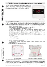
TM-201A
Бренд: jablotron Страницы: 6

DT-W
Бренд: Heatmiser Страницы: 20

EvenAir TSRC
Бренд: Field Controls Страницы: 8

OMG 812
Бренд: Taylor Страницы: 6

ALFA 71 S PI
Бренд: VDH Страницы: 4

TRACEABLE 3650
Бренд: Control Company Страницы: 2

BAC-1000 series
Бренд: BECA Страницы: 18

HC-EARTHERM60
Бренд: König Electronic Страницы: 68

FTM501
Бренд: Blaupunkt Страницы: 34

UC300
Бренд: domat Страницы: 8

TSTBM-RRS--TW-A
Бренд: Bosch Страницы: 16

TSTBM3H2CPH6W-A
Бренд: Bosch Страницы: 32

Smart Home Thermostat AA
Бренд: Bosch Страницы: 12

TSTBT4H2CP-M--A
Бренд: Bosch Страницы: 24

TR 200
Бренд: Bosch Страницы: 88

TRZ 12 T
Бренд: Bosch Страницы: 84

TRZ 12-2
Бренд: Bosch Страницы: 84

Braeburn
Бренд: Ferguson Страницы: 2


