background image


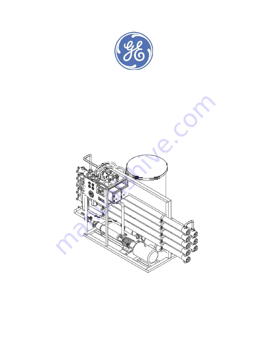
OPERATIONS  AND MAINTENANCE  MANUAL 


E4H Series Water Purification  Machines 


16,000 GPD to 43,200 GPD 

60.6 m

3

/day to 163.5 m

3

/day 


NOTICE 


The enclosed materials are considered proprietary property of GE Water & Process Technologies. No assignments, either implied or expressed, of 
intellectual property rights, data, know-how, trade secrets or licenses of use thereof are given. All information is provided exclusively for the addressee for 
the purposes of evaluation and is not to be reproduced or divulged to other parties, nor used for manufacture or other means, or to authorize any of the 
above, without the express written consent of GE Water & Process Technologies. The acceptance of this document will be construed as an acceptance of 
the foregoing conditions. * Trademark of General Electric Company; may be registered in one or more countries. 

Summary of Contents for E4H-16K

Page 1: ... trade secrets or licenses of use thereof are given All information is provided exclusively for the addressee for the purposes of evaluation and is not to be reproduced or divulged to other parties nor used for manufacture or other means or to authorize any of the above without the express written consent of GE Water Process Technologies The acceptance of this document will be construed as an acce...

Page 2: ...rane Elements 6 1 1 6 CIP 8 1 1 7 Average Pressure PAVG 8 1 1 8 Concentration 8 1 1 9 Salt Ionic Passage 8 1 1 10 Recovery 8 1 1 11 Salt Ionic Rejection 8 1 2 Flow Description 10 1 3 Machine Nomenclature 10 1 4 Economy ECN Model and Deluxe DLX Model Options 11 1 4 1 ECN Model 11 1 4 2 DLX Model 12 1 5 Specifications for E Series Machines 13 1 5 1 Feed Water Specifications 13 1 5 2 Permeate Flow Ra...

Page 3: ...AND START UP 19 3 1 Pretreatment for Water Purification 19 3 2 Start Up 20 4 OPERATION AND MAINTENANCE 26 4 1 Daily Log Sheets 26 4 2 Pre Filter 26 4 3 Flushing 27 4 4 Cleaning 28 4 4 1 CLEANING PROCEDURE FOR DLX AND ECN MODELS 28 4 5 Draining Machine for Storage Shipment 30 4 6 Membrane Installation 30 4 7 Membrane Replacement 32 5 OPTIONAL ACCESSORIES 33 5 1 Standard Options 33 5 2 External Cont...

Page 4: ...ATA 50 10 2 DAILY LOG FOR GE WATER PROCESS TECHNOLOGIES MEMBRANE MACHINES 51 List of Tables Table 1 1 Flow Specifications for E4H Machines 50 75 Recovery 13 Table 1 2 Feed Water Requirements 13 Table 1 3 Membrane Element Specifications AG4040F 15 Table 2 1 Connection Schedule 17 Table 6 1 Troubleshooting Guide 35 List of Figures Figure1 1 Normal vs Crossflow Filtration 6 Figure1 2 Membrane Element...

Page 5: ...Concentrate Rate Reject Rate Qc The flow rate of water containing rejected solids to drain in gpm or gph lpm or m3 h 1 1 3 Feed Rate Qf The flow rate of incoming water in gpm or gph lpm or m3 h Feed water rate equals permeate rate plus concentrate rate 1 1 4 Reverse Osmosis RO Reverse osmosis is the separation of one component of a solution from another component by means of pressure exerted on a ...

Page 6: ...ed around a central permeate tube make up the element The spacer allows for movement of the concentrate past the membrane and the permeate carrier carries the purified water out of the membrane element GE Water Process Technologies manufactures a patented spiral wound membrane element with a turbulent flow design This membrane module collects the purified water within the central tube the permeate...

Page 7: ...Operations and Maintenance Manual E4H Series Water Purification Machine 7 Figure1 2 Membrane Element with Interconnectors Figure1 3 Cross Sectional View of Membrane Element ...

Page 8: ... Feed Concentration Cp Permeate Concentration Cc Concentrate Concentration Cavg Average Concentration in Machine 1 1 9 Salt Ionic Passage The percent of dissolved salts passed through the membrane or 100 minus rejection 1 1 10 Recovery Permeate rate divided by feed rate expressed as a percentage For example 33 recovery means that for a given feed rate 33 is produced as purified water permeate 1 1 ...

Page 9: ...nd recovery is given below Figure1 4 Principle of Operation Given the system case in the figure above Average Concentration 2 C C C c f Avg TDS 237 5mg L 2 375mg L 100mg L 5 96 100 237 5mg L 8 3mg L 237 5mg L 100 C C C Rejection Avg p Avg 5 3 100 237 5mg L 8 3mg L C C Passage Avg p 75 100 24gpm 18gpm 100 Q Q Recovery f p ...

Page 10: ...ermeate and concentrate Permeate from each membrane housing is collected in a common manifold The permeate then flows through a flow meter and to the outlet point of the machine The concentrate leaves the last membrane housing and flows to the flow control center recycle concentrate manifold At this point the recycle valve channels a predetermined amount of concentrate into the pump inlet Recycle ...

Page 11: ...d 380 VAC 50 Hz 3 phase 6 indicates 60 Hz operation 50 Hz operation is also available and is indicated by a 5 in place of the 6 50 75 indicates a recovery range of 50 to 75 1 4 Economy ECN Model and Deluxe DLX Model Options 1 4 1 ECN Model E Series ECN model water purification machines have all the features necessary for safe continuous production of high purity water This assumes good quality fee...

Page 12: ...nd caps Stainless steel concentrate and recycle valves All components in contact with the purified water permeate are either FDA acceptable plastic nylon Noryl polypropylene PVC or stainless steel materials All high pressure fittings are 304 stainless steel Alarms included low inlet pressure and motor fault 1 4 2 DLX Model The DLX package contains all of the above ECN standard features along with ...

Page 13: ... 1 8 5 5 7 52 4 34 9 11 9 7 9 60 40 13 6 9 1 1 5 1 Feed Water Specifications The feed water requirements stated in the following table must be met to ensure quality permeate and extended membrane element life Table 1 2 Feed Water Requirements Temperature Typical 50 85 F 10 29 C Maximum 32 104 F 0 40 C Inlet Pressure Minimum 30 psig 2 1 bar Maximum 60 psig 4 1 bar Chlorine continuous feed 0 ppm Ope...

Page 14: ...ng re Backpressu Permeate Pressure Operating Label on Flow Permeate 1 5 3 Concentrate Flow Rate Stated in Table 1 1 and factory set as stated on serial number label 1 5 4 Operating Final Pressure Minimum 200 psig 13 8 bar Maximum 235 psig 16 2 bar 1 5 5 Pump Multi stage centrifugal approximate primary operating pressure of 190 psig 13 1 bar excluding line pressure 1 5 6 RO Membrane Rejection E4H r...

Page 15: ... psi 2 200 gpd 8 3m3 day Typical Feed Water Temperature Range 50 85 F 10 29 4 C Maximum Temperature 122 F 50 C pH Range 4 0 11 0 Chlorine Tolerance 0 01 ppm Active Membrane Area 85 ft2 7 9 m2 Specification is based on a 2 000 mg L NaCl solution at 225 psi 1 551 kPa operating pressure 77 F 25 C pH 7 5 and 15 recovery Individual flux may vary 25 15 Average salt rejection after a minimum of 24 hours ...

Page 16: ...nstalled at the highest point along the concentrate line Failure to do so may cause a vacuum to form within this line after shutdown This may in turn cause numerous problems including biological fouling water hammer leaks from RO housing side ports and the siphoning of treatment chemicals WARNING Connect the concentrate line to the RO machine s concentrate outlet A vacuum breaker must be installed...

Page 17: ...t is separate from the motor voltage Therefore two supply voltages are required for electrical wiring in the field the control circuit voltage and a separate three phase motor voltage All field wiring must comply with applicable local and national electric codes 2 3 1 ECN Electrical System A panel mounted power on off switch is provided on the electrical enclosure Connect the control circuit power...

Page 18: ...control circuit power to 110 VAC 60 Hz or 220 VAC 50 Hz single phase power Connect the three phase power in to the motor starter 3 pole contacts 230 460 VAC or 380 VAC as appropriate Ensure that the power supplied matches the motor voltage and phase requirements Check the tag located on the motor starter that indicates the factory wiring A separate fused disconnect for the motor wiring is required...

Page 19: ...puter program analysis to determine if potential problems exist If the machine is to be run at a different location than was originally intended a new water analysis is required for warranty consideration and should be sent to GE Water Process Technologies for review and recommendations for operation of the machine Before entering the machine the feed water must be filtered to 5 microns TFC membra...

Page 20: ...at all connection points 4 Turn on the feed water gradually and check for leaks in the inlet piping No flow should go through the machine while the power is off and the inlet solenoid is in the closed position When the machine is off there should never be flow through the machine Flow through the machine when it is off can damage the membranes and the inlet solenoid m u s t b e repaired NOTE 5 Att...

Page 21: ...tes the operating pressure shown on the pressure gauge The recycle valve returns reject flow back into the inlet stream to the RO pump It is important to balance the operating pressure and the respective flows of these valves to ensure that your machine is operating correctly It is also important to understand the relationship of these two valves the pressure gauge and your RO pump The pump has a ...

Page 22: ...ints are as follows consult the AccuTrak RO Multifunction Water Treatment Controller Manual for operating instructions and additional information Low Inlet Pressure 12 psig High Permeate Pressure 80 psig Permeate Conductivity 200 µS microSiemen Low pH 4 0 High pH 8 0 pH Control 5 6 6 2 High Temperature 104 F 40 C 16 As your machine is filling check for leaks and repair as needed 17 Turn the AccuTr...

Page 23: ...ls with water the pressure will gradually increase You should see water flowing through the permeate and concentrate flow meters If you do not see flow turn the machine off and return to step 1 NEVER ALLOW THE MACHINE TO OPERATE WITHOUT ADEQUATE WATER PRESSURE THIS CAN CAUSE SEVERE DAMAGE TO THE HIGH PRESSURE PUMP 19 Gradually close the concentrate flow control valve As you close the valve watch t...

Page 24: ...tting alternate flow rates for variable recoveries If you wish to operate at a recovery lower than 75 you must ensure that the flow rates for the permeate and concentrate are at desired levels Some minor adjustments in the concentrate and recycle flow control valves may be necessary See Table 1 for specified flow rates for various machine recoveries When you have selected your desired flow rate gr...

Page 25: ...re rated for certain flow rates at 77ºF 25ºC Maximum flow rates are achieved when the membranes have been completely rinsed and on line for at least 24 hours 27 Record all operating parameters at initial startup on a log sheet A start up data log sheet is included in section 9 3 of this manual 28 A daily log sheet which includes general operating conditions pressures flows concentrations pH and pr...

Page 26: ...hine with approved GE Water Process Technologies cleaners See the following sections for specific maintenance procedures 4 1 Daily Log Sheets A daily log sheet which includes general operating conditions pressures flows and concentrations and routine or special maintenance pre filter changes flushing cleaning etc must be kept Copies of the log can be made from the template A copy of this log sheet...

Page 27: ... to AUTO mode in the deluxe version and when the ON OFF switch is set to ON in the economy version This eliminates the need for frequent manual flushing NOTE To flush the unit 1 Open the concentrate valve until the pressure gauge indicates the minimum pressure designated on the nameplate This increases the flushing action on the membrane NOTE If pressure will not decrease to designated pressure or...

Page 28: ...CLEANING PROCEDURE FOR DLX AND ECN MODELS 1 With the RO machine running open the CIP permeate valve After this valve has been opened close the permeate service valve Permeate water will flow into the CIP tank Allow the water to run through the CIP tank and the CIP tank drain valve for a few minutes to ensure the tank is rinsed thoroughly After a minute or so close the CIP tank drain valve The CIP ...

Page 29: ... the CIP pump discharge plumbing to the Victaulic fitting on the CIP inlet just upstream of the RO pre filter Connect CIP concentrate and permeate hoses from the RO to the CIP tank supplied by others Open the CIP recirculation valve so as to create 15 psig back pressure to the CIP pump Turn on the CIP pump and recirculate the cleaning solution in the CIP tank for 5 minutes Open the CIP hand valve ...

Page 30: ... storing the machine is responsible for any damage resulting from freezing 1 Disconnect the inlet concentrate and permeate outlets 2 Drain all water from the cartridge filter housing 3 Remove the tubing connections on the inlets and outlets of the membrane housings 4 Open the concentrate valve 5 Remove the drain plugs from all PVC manifolds 6 Be sure the flow meters are drained by disconnecting th...

Page 31: ...brane housing and clean as necessary to remove any contaminants obstructions etc 8 Apply a small amount of O ring lubricant to all O rings on the end caps and the brine seal on the membrane 9 Insert the downstream end of the membrane in the upstream end of the membrane housing i e load in the direction of flow the brine seal is on the end of the membrane that goes in last For membrane housings wit...

Page 32: ...ter one year of operation but can be extended with diligent flushing and cleaning of the machine High pH feed water and or precipitation of hardness can cause premature loss in rejection and even flow rate The following procedure is to be followed to replace existing membranes in the machine 1 Remove the end caps from all of the membrane housings 2 Remove all of the membranes from the membrane hou...

Page 33: ...rane elements with low energy elements Replaces standard RO pump with lower pressure pump Result is machine will produce rated permeate flow at 77 F 25 C but at an operating pressure of approx 115 psi 8 bar Note Design is already standard on E4 LE Series 5 Nanofiltration NF Reverse Osmosis RO membrane elements Replaces standard membrane elements with NF elements The machine will operate at approx ...

Page 34: ...ry supplied terminals Refer to either the DLX or ECN electrical drawings for proper wiring and or electrical connections 5 3 Filters and Water Softeners Backwashable filters and softeners should be installed such that unfiltered or unsoftened water will not be fed to the machine while the RO unit is operating Failure to do this may cause fouling or precipitation of calcium carbonate or other mater...

Page 35: ... 6 1 Troubleshooting Guide Symptom Alarm Possible Cause Remedies Low inlet pressure low inlet alarm Insufficient feed water pressure Increase the feed pressure open the inlet feed valve check for restrictions and consider installing a feed water boost pump Clogged pre filter Replace the pre filters Solenoid valve not opening Clean or replace the solenoid valve Low operating pressure High flow rate...

Page 36: ... rate manually with a stopwatch and calibrated container such as CIP tank Valve position Check CIP and outlet valve positions for correct orientation Low concentrate flow rate normal or higher than normal pressure Concentrate valve plugged Disassemble and the clean the plumbing to the valve Concentrate outlet line restricted Examine the concentrate line for obstructions or a closed valve Flow sens...

Page 37: ...branes immediately Water must not pass through the inlet when the machine is off Repair or replace valve components as necessary Declining rejection high permeate conductivity Dirty or fouled membranes Clean the membranes O ring seal broken or damaged Replace the O ring check the sealing surfaces on the O ring groove interconnectors and end caps Replace damaged parts NOTE This typically only happe...

Page 38: ...ump not operating properly See the pump instructions Contact GE for repair of replacement Alarm condition has turned off machine Check for minimum inlet pressure and push alarm reset switch Electrical machine shutdown Alarm condition has turned off machine Restart the machine by pushing the alarm bypass Check all possible alarm conditions inlet pressureand push alarm reset switch External control ...

Page 39: ...ring data Logging Did Error message No SD Card detected appear If not check the free memory capacity If the SD card memory is not full the SD card has to be exchanged AccuTrak RO error CalibFault 4 20mA In Input State Fc Defect Calibration data for at least one configured 4 20 mA Pt100 Input Contact local GE Service AccuTrak RO error CalibFault PT100 In Input State Fc Defect Calibration data for a...

Page 40: ...eter data is reset to default values and the AccuTrak RO can operate no longer as controller The continuation of the operating as controller is possible after the downloading of a new configuration and parameterization Sensor Fault Input State FS Analog inputs 4 20 mA current above approx 20 5 mA Pt100 resistance input range Check the wiring from the corresponding sensor to AccuTrak RO ...

Page 41: ...Operations and Maintenance Manual E4H Series Water Purification Machine 41 ...

Page 42: ...tenance Manual E4H Series Water Purification Machine 42 7 SPARE PARTS LIST For detailed spare part lists please refer to the manual addendum Contact the GE Water Process Technologies Customer Support Center to order parts ...

Page 43: ...Operations and Maintenance Manual E4H Series Water Purification Machine 43 ...

Page 44: ...ons and a return authorization number which needs to be clearly written on the outside of the box used to ship your materials All equipment must be shipped to GE Water Process Technologies with the freight prepaid by the customer Call our Customer Support Center with any questions or issues concerning freight claims and a representative will discuss your situation IMPORTANT Machines must never be ...

Page 45: ...Operations and Maintenance Manual E4H Series Water Purification Machine 45 ...

Page 46: ... all liabilities for use and misuse by buyer its agents or assignees Buyer shall give immediate notice in writing to Seller if products or components thereof or performance where applicable appear defective and shall provide Seller with reasonable opportunity to make inspections tests and repairs using the most efficient and cost effective methods available for such products or components If Selle...

Page 47: ...erated in accordance with written instructions for a period of one year from start up or fifteen months from receipt whichever is shorter Parts not manufactured by GE Osmonics are covered by their manufacturers warranties that are normally for one year GE Osmonics spiral wound membrane elements are guaranteed to operate within specifications when used for general water treatment for a period of 12...

Page 48: ...embrane element not meeting specifications Should GE Osmonics not receive notification of non compliance with performance specifications within said thirty 30 day period GE Osmonics will consider that all membrane elements are accepted All membrane elements being returned for non warranty issues or credit for unused membrane elements must be returned unused in their original packing Membrane eleme...

Page 49: ...ating data records GE Osmonics may request these records in the warranty evaluation User must notify GE Osmonics at the very first sign of changes in operation of the Osmo machine or membrane elements Such notification should be in writing and should include all data requested on the operating log sheets GE OSMONICS EXPRESSLY DISCLAIMS LIABILITY FOR INCIDENTAL AND OR CONSEQUENTIAL DAMAGES INCLUDIN...

Page 50: ...ermeate Rate gpm lpm Concentrate Rate gpm lpm Total Flow Rate gpm lpm Recovery Pre Filter Pressure psi bar Post Filter Pressure psi bar Primary Pressure psi bar Final Pressure psi bar Feed Conductivity µS cm Concentrate Conductivity µS cm Average Conductivity µS cm Permeate Conductivity manual µS cm Permeate Conductivity meter µS cm Passage Perm TDS Avg TDS Chlorine in Concentrate Ppm Low Pressure...

Page 51: ...ystem PERMEATE PERMEATE QP TEMP TEMPERATURE COND CONDUCTIVITY DATE AND TIME PRE FILTER PRESSURE psi or bar POST FILTER PRESSURE psi or bar PRIMARY PRESSURE psi or bar FINAL PRESSURE psi or bar FEED WATER TEMP F or C PERM FLOW gpm or lpm CONCENTRATE FLOW gpm or lpm RECOVERY QP QP QC FEED COND µS CONC COND µS PERM COND µS AVERAGE COND µS CF CC 2 FILTER CHANGE CLEAN FEED CHLORINE ppm FEED WATER HARDN...

Page 52: ...s Trevose PA 1 215 355 3300 Americas Watertown MA 1 617 926 2500 Europe Middle East Africa Heverlee Belgium 32 16 40 20 00 Asia Pacific Shanghai China 86 0 411 8366 6489 Copyright 2014 General Electric Company All rights reserved PrintedinUSAMaterial P N 1163955RevE Document P N 1304629 Rev E ...

Reviews: