Gazelle G9701, User Manual
The Gazelle G9701 is a top-notch product, capable of delivering exceptional performance. To fully utilize its features and functionalities, make sure to have the comprehensive User Manual by your side. Download it for free at manualshive.com and explore all the incredible aspects of this remarkable device.
Share
Download


Reviews:
No comments
Related manuals for G9701

4.0
Brand: Tactacam Pages: 17
Z3
Brand: Z-EDGE Pages: 4

iGO CAM 600
Brand: Uniden Pages: 20
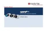
PI 640
Brand: optris Pages: 92

BT53328
Brand: Yada Pages: 20

GDVR110
Brand: Gator Pages: 18

Vue TZ20-R
Brand: FLIR Pages: 26

CDR 830
Brand: Cobra Pages: 2

CD 855 BT
Brand: Cobra Pages: 8

CDR 820
Brand: Cobra Pages: 13

CDR 840
Brand: Cobra Pages: 31

D12
Brand: YEECORE Pages: 38

RNEK-MN31B
Brand: LG Pages: 15

LGD521
Brand: LG Pages: 26

058465799687
Brand: ProScan Pages: 18

31647
Brand: Berger+Schröter Pages: 25

Lockpick C8R
Brand: Coastal Electronic Pages: 8

X1
Brand: Kaiser Baas Pages: 13


