Garmin GTX 23, Installation Manual
The Garmin GTX 23 is a high-performance aviation transponder that provides seamless integration with your aircraft's existing systems. Ensure a smooth installation process with the comprehensive Installation Manual, available for free download from our website. Maximize your Garmin GTX 23 experience today!
Share
Download


Reviews:
No comments
Related manuals for GTX 23

airFiber AF-5XHD
Brand: Ubiquiti Pages: 30

airFiber AF-24
Brand: Ubiquiti Pages: 50

PTT
Brand: B&G Pages: 2

VLB-5X
Brand: Vega Industries Pages: 53

Solid Digital
Brand: perfect pro Pages: 32
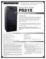
ProPower PS215
Brand: Nady Audio Pages: 2

9400 UX
Brand: Alcatel Pages: 102

WS-8157U
Brand: La Crosse Technology Pages: 21

SXMLCR72
Brand: Pixel Pages: 4

NS-CL02
Brand: Insignia Pages: 24

EMCBK1
Brand: Enrock Marine Pages: 2

WFR-2D
Brand: Sangean Pages: 84

FRX3+
Brand: Eton Pages: 40

cNODE MiniS 1.11-50V Ti
Brand: Kongsberg Pages: 48

DSR-6100
Brand: Motorola Pages: 6

TRITON 20
Brand: Motorola Pages: 61

DSR-6100
Brand: Motorola Pages: 98

RC606
Brand: Hyundai Pages: 28


