


Installation and operating instructions
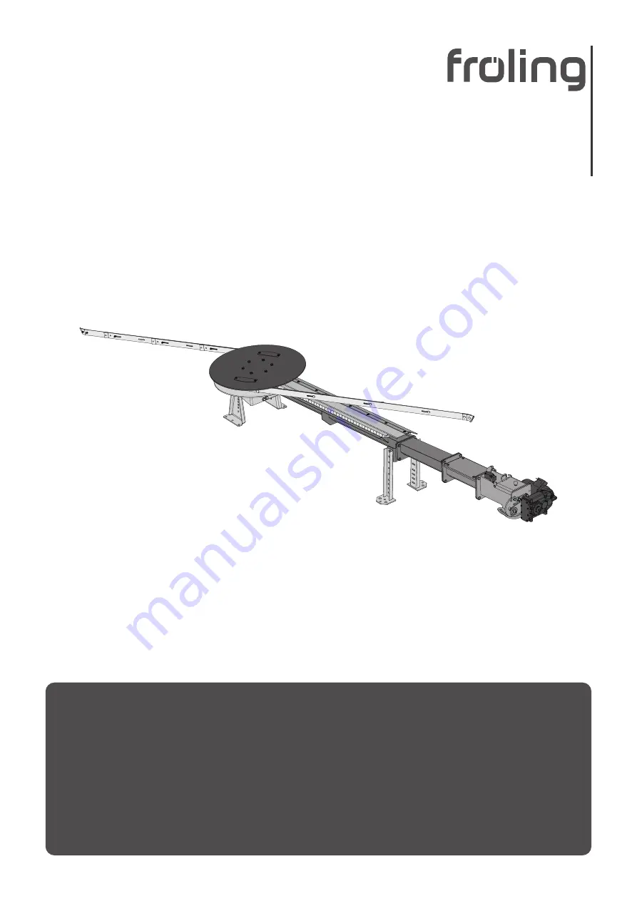
Spring blade agitator FBR
Translation of original German version of installation and operating instructions for technicians and
operators.
Read and follow all instructions and safety instructions.
All errors and omissions excepted.
M0741021_en | Edition 18/10/2021


