


1
SERVICE DATA SHEET
318127023 (0505) Rev. A
Gas Slide-in Range with Electronic Oven Control
SAFE SERVICING PRACTICES
To avoid the possibility of personal injury and/or property damage, it is important that safe servicing practices
be observed. The following are examples, but without limitation, of such practices.
1. Do not attempt a product repair if you have any doubts as to your ability to complete it in a safe and
satisfactory manner.
2. Before servicing or moving an appliance, remove power cord from electric outlet, trip circuit breaker to Off,
or remove fuse and turn off gas supply.
3. Never interfere with the proper installation of any safety device.
4. USE ONLY REPLACEMENT PARTS CATALOGED FOR THIS APPLIANCE. SUBSTITUTIONS MAY DEFEAT COMPLIANCE
WITH SAFETY STANDARDS SET FOR HOME APPLIANCES.
5. GROUNDING: The standard color coding for safety ground wires is GREEN OR GREEN WITH YELLOW STRIPES.
Ground leads are not to be used as current carrying conductors. IT IS EXTREMELY IMPORTANT THAT THE
SERVICE TECHNICIAN REESTABLISH ALL SAFETY GROUNDS PRIOR TO COMPLETION OF SERVICE. FAILURE TO
DO SO WILL CREATE A POTENTIAL HAZARD.
6. Prior to returning the product to service, ensure that:
• All electric connections are correct and secure.
• All electrical leads are properly dressed and secured away from sharp edges, high-temperature components,
and moving parts.
• All non-insulated electrical terminals, connectors, heaters, etc. are adequately spaced away from all
metal parts and panels.
• All safety grounds (both internal and external) are correctly and securely reassembled.
• All panels are properly and securely reassembled.
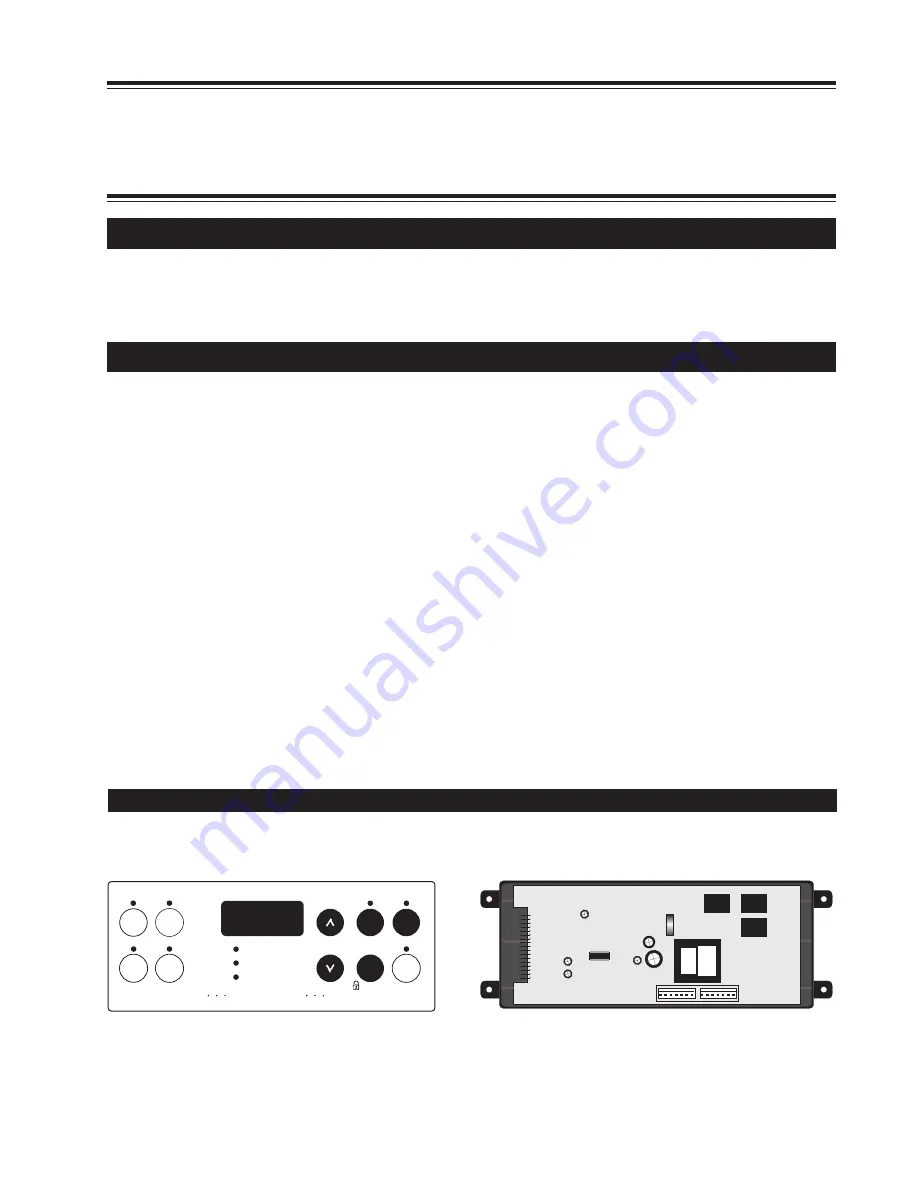
ELECTRONIC OVEN CONTROL
The ES300 electronic oven control is almost identical to the current control with a few exceptions.
Note:
The ES300's are not field repairable. Only temperature settings can be changed. See Electronic Oven
Control Guide (section recalibrating your oven temperature).
Note:
Depending on model, the size and shape of touch pads may vary (for example round instead of elliptical).
1
P5
15
This service data sheet is intended for use by persons having electrical and mechanical training and a level of
knowledge of these subjects generally considered acceptable in the appliance repair trade.
The manufacturer
cannot be responsible, nor assume any liability, for injury or damage of any kind arising from the use of
this data sheet.
NOTICE
Start
time
Bake
time
Timer
On/Off
Clock
Bake
Broil
Clear
/Off
Controls
Clean
Self-Cleaning Oven
Oven
Preheat
Door Locked


