Fluke 51, Service Manual
The Husqvarna 51, a powerful yet compact chainsaw, is a reliable tool for homeowners and professionals alike. Enhance your knowledge and operating skills with the detailed Owner's Manual available for free download at manualshive.com. This comprehensive manual ensures safe and efficient operation, maximizing the performance of your Husqvarna 51.
Share
Download


Reviews:
No comments
Related manuals for 51

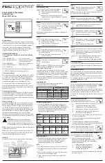
EB-Therm 205
Brand: EBECO Pages: 4

ALFANET 85
Brand: VDH Pages: 8

683F03
Brand: RF Tech Pages: 2

STC-9200
Brand: Haswill Pages: 2

ALFANET 95
Brand: VDH Pages: 8

AMRc-1
Brand: JUMO Pages: 2

SZ1017a
Brand: TCS Basys Controls Pages: 18
PERFECTSENSE PS3110 Series
Brand: Uni-Line Pages: 3

TPR301
Brand: Ewig Macao Pages: 9

3140
Brand: Summer Pages: 4

Hart Scientific 5626
Brand: Fluke Pages: 22

64 max
Brand: Fluke Pages: 35

DT150
Brand: UEi Pages: 6

62 MAX
Brand: Fluke Pages: 22

Hart Scientific 1522
Brand: Fluke Pages: 60

C365T21
Brand: Comfort365 Pages: 8

ComfortSense 3000 Series
Brand: Lennox Pages: 16

ECO910
Brand: ensto Pages: 16


