


© 2018 Flamco group. All rights reserved.
We reserve the right to change designs and technical specifications of our products.
Errors and omissions excepted.
Rev 1.0 Aug-18
Page
1
/
44
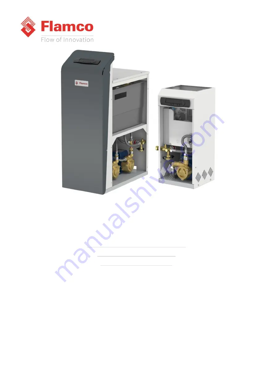
Flamco Pro Range Pressurisation Equipment
Pro PU (131, 231, 161, 261, 181, 281)
Pro PUm (131, 231, 161, 261)
Pro PDm (1.0, 1.5, 2.0, 2.5)
Operation & Maintenance Manual


