Five CDC11, User Manual
Introducing Five CDC11 - a cutting-edge device designed for seamless connectivity. Enhance your user experience with an informative User Manual, providing step-by-step instructions. Download this manual for free from our website manualshive.com, unlocking the full potential of your Five CDC11, hassle-free.
Share
Download


Reviews:
No comments
Related manuals for CDC11

KISS
Brand: Hamax Pages: 74

AR-FN6
Brand: Olivetti Pages: 39

S02
Brand: NAKTO Pages: 24

KX-TD816JT
Brand: Panasonic Pages: 242

be cool boosty
Brand: JANE Pages: 21

SANTA FCB-XM-CH0084-120V
Brand: GE Pages: 2

STACK101
Brand: Stack Pages: 2

Astro & Nature
Brand: Baader Planetarium Pages: 6

Heathkit SA-5010
Brand: Heath Pages: 3

00178266
Brand: Hama Pages: 75

595B
Brand: Manfrotto Pages: 2

GENERIC 8400
Brand: Burkert Pages: 126

T-RAMP
Brand: Condor Pages: 2

GCR53F
Brand: Gatorback Mudflaps Pages: 4

DUFTDOS-AK1
Brand: WDT Pages: 34

LoRaWAN CARBONLESS
Brand: nano sensorics Pages: 7

PT-E03
Brand: Olympus Pages: 41
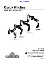
QH05 Series
Brand: Land Pride Pages: 38


